
In my last article, I spoke about the benefits of midplane meshing in sheet metal components. Today, I’d like to discuss another topic from the odds and ends I collected, and talk about gravity loading of plate structures and how that affects the natural frequency of sheet metal components.
Natural Frequency Modes and Gravity Loaded Stiffening
Applied loads to a meshed plate model will affect the mode shapes and displacement magnitudes, Right?
Well, yes if it is a point load. However in the case of gravity affecting the plate, the load does not affect the natural frequency response. Gravity, normal to a flat plate model results in a pure bending situation.
If you take a meshed plate model, flat with the horizon, constrained at both ends, and load it with gravity, there will be no appreciable difference in mode or shape from that of a no-load modal analysis. The reason is that the loading from gravity is treated as a surface load, distributed equally among all its nodes. As the nodes react to the constraints and degrees of freedom, they expand and contract radially in relation to the median plane of the plate (centerline). This creates ‘pure bending’, where the upper side of the plate experiences a compression strain equally opposing a tension strain on the opposite side. The result is a 0 gain of tension along the median plane of the plate.
Tension, I was reminded by my friends at Autodesk’s Sim Squad, is what affects the mode shapes in a structure. With no relative change in tension, there is no change in mode.

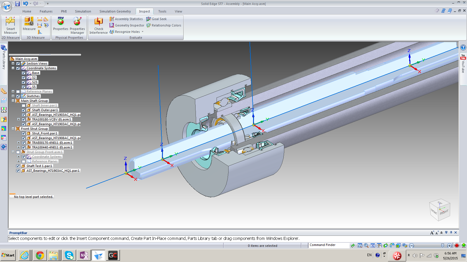
In the image above I have taken the same model from the SEM study below, and added it to a static stress analysis, in order to measure the tension in the plate. After applying both translating and non-translating constraints, as well as standard gravity normal to the surface, I get consistent results. Notice the probe values in the center of the image. Equal compression and tension. This is the case at every point along the model.
Modes
I performed similar comparative studies on a smaller sheet of A36 Steel. The image below depicts the 5th mode (3,1) encountered on the same sheet of steel, using Simulation Mechanical to perform the analysis 3 different ways..

The modes are identical, no matter how much normal gravity loading is applied.
However, when we turn gravity off axis, the modes begin to change.

Comparing Simulation Mechanical to SEM Results
I decided to study a bit further on the behavior of plates and natural frequencies. I came across a study of the Spectral Element Method (SEM) in a book titled “Spectral Element Method in Structural Dynamics”, by Usik Lee. The book details the mathematics and theories involved, however to understate things quickly, the mathematics involved consider the entire plate as a single element, with fast and accurate results in plate objects. The results are surprisingly close to that of other methods in the given circumstances (nothing works in all cases). The book also details the results found in another reference of theoretical responses, as well as the Finite Element Model method.
So I wanted to compare the results of Simulation Mechanical against those in the study. This particular example is a sheet, 1m x 15m x 0.003m in dimension, with the properties similar to AISI 4130 steel, and being tensioned along the long axis of the sheet by a force of 60kN. I used a midplane plate formulated with Reduced Shear elements, and divided the sheet into the same division in the study’s FEM model, 8 x 120 elements. The leading and trailing ends were constrained without axial rotation constraints, and the 60kN load was applied. (See notes below).
I wanted to see how the sheet behaved without gravity, with gravity loaded normal to the plate surface, and with gravity loaded along the long axis of the sheet. The mode shapes are identical to those shown in the study without exception.

In the image above, the mode shapes compared to the study are identical. These can be found on page 207 of the book, figure 7.12 “natural modes of the stationary plate subjected to Nx = 60kN/m”.
The comparative results are further detailed below. Notice how gravity plays no part in the modes of the plate when it is directed normal to the sheet. However once gravity is turned off-axis, the mode shapes begin to change. This is due to the tension difference on the sheet produced by the change in applied axial loading.

Additionally, Simulation Mechanical’s natural frequency analysis performed quite well against the study’s different methods of calculation (0.4% max deviation related to SEM).
Notes related to the study
Theoretical results in the study were taken from a book referenced as [24] Blevins, R.D. (1979) Formulas for Natural Frequency and Mode Shape,Van Nostrand Reinhold Co, NewYork.
Material properties assigned in the comparison were taken from the SEM book on page 206, defined in Example 7.4. The properties were 15m x 1m x 0.003m, Young’s Modulus E = 200 GPa, Poisson’s Ratio v = 0.333, Density p = 7800 kg/m^3.
The results here are related to a plate supported by theoretical rollers separated by the length stated. After careful examination, the results indicate that the study was performed without axial rotation constraint along the leading and trailing edges. Should ‘”supports” have been used as proposed in the study and the length of plate actually longer (as shown in the diagram indicated), the rotational freedom of the leading and trailing edges would have been constrained. While the results between the variations are similar, the magnitude of differences (1.9 – 2.6%) suggest axial freedom of rotation along the far edges.

