Recently Garin Gardener posted a podcast on 3D sketching. Normally I would bypass this topic, but I decided to give it a look. I’m happy I did.
It was such a good podcast, that I decided to highlight the big stuff rather than just linking you to it. I put a bit more detail into my sketches, to show a few other details along the way.
The discussion covered the following:
- 3D sketching in 2D and the effects of a sweep feature
- 3D sketching in 3D and the effect of a sweep feature
- 3D Intersection Curve (we’ll cover this topic later)
3D sketching in 2D
One way to prepare a 3D sweep, is by constraining various 2D sketches together, that are created on different planes.
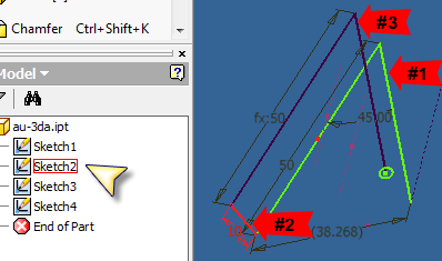
In the following example, you should be able to see there are 4 2D sketches, all created on different workplanes (planes visibility is hidden):
1-3 are constrained at endpoints, and #4 is the profile for the sweep.

When we create the shell feature, it will select all unconsumed sketch curves that are constrained together in 1 pick. Notice also that it will not select curves that have been set as construction geometry.

Here is the result. Another point that was brought up was that fillet edits cannot be created between the curves on different 2D sketches.

3D sketching in 3D
I pushed the end of part marker up above the sweep feature, and set the visibility on for the consumed sketch 1. After creating a new 3D sketch, I set the view parallel to the X-Y plane, by selecting the FRONT of the view cube.

Notice the following image. Once you begin a sketch feature (I started the line tool), the precise input toolbar appears, and the origin glyph snaps relative to the location at the start of the feature (where I picked to start the line). Notice the planes attached to the origin.

As you move your cursor over each of these, they highlight awaiting your selection. Once selected, Inventor constrains the 3D sketch down to that plane as if it were a 2D sketch. Temporarily. As soon as the feature(s) is completed, the sketch grid is turned off.

I created the curves, using the construction geometry from the 2D Sketch #1 to start from. Once I had constrained and dimensioned everything, I used the bend tool, to create the curved features I wanted. Since I was at the end of the sketching along the X-Y Plane, I needed to go vertical.
I pushed the cursor over the origin glyph, and selected the plane shown below.

I was then constrained to that plane. Quite temporarily.

Once I got to the location shown in the image above, I was inclined to stop and add a dimension and a constraint, but as soon as I did, the curves began to warp 3D!.
The Fix constraint!
I constrained the previous ‘bottom’ segment to be fixed, and that did it. Form there everything else could be constrained and dimensioned. I started the remaining sketch geometry from the last endpoint, selected the front plane from the origin glyph, and finished up.

Note that while we cannot create fillet edits between different 2D sketches, we can create bends in 3D sketches.

So let’s create another work plane and sketch to set the profile for the last sweep, at the end of the 3D sketch feature, and select the 3D path. Notice the entire path is selected here in 1 pick.

Drop the end of part marker, and you have my new neon sign.

Ok…Ok.. Yeah I really overworked the information from the podcast, but I wanted to have some fun.
The things to take away from this I think are the following:
- Remembering to project the needed geometry from 1 2D sketch to another, and constraining them together.
- The plane reference on the origin glyph in 3D sketches is great.
- Fix selected geometry in 3D sketches to keep control.
I will touch on 3D intersection curve next time.

