
Autodesk Inventor’s patterning tools allow you to duplicate objects in an ordered arrangement. You can pattern in different layouts, like in a rectangular grid. Patterning saves you time by being quick in duplicating geometry. Additionally, the way Inventor processes patterns results in models that are more efficient and perform better than those created by simply copying features.
I previously explored assembly patterns. But in Inventor, you can also pattern part features and sketch geometry.
Inventor Patterns (Feature Edition)
Autodesk Inventor’s part feature patterns duplicate existing features, like holes and extrusions, but can also include placed features like fillets. You can also pattern bodies in a multibody part.
When patterning features, you have three options: Rectangular, Circular, and Sketch Driven.

Regardless of which command you select, Inventor opens the same palette but activates a different tab. You can switch between types from the toolbar. You can also toggle between selecting features and selecting solids.
Starting with Inventor 2026, patterns use the modern palette. Previously, the pattern interface was a dialog resembling the assembly pattern feature.

For all three types, the first step is selecting the features (or solids). Secondary features, like fillets and chamfers, can only be patterned if you are also patterning their parent host objects.
Rectangular Patterns
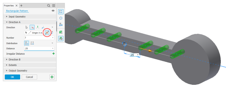
Rectangular patterns arrange the selected features into rows and columns. You set the Direction and Number. The direction sets the directions of the rows and columns. The number is how many occurrences (including the original) to copy in the direction. The number must be greater than zero.

The directions do not need to be perpendicular and, in fact, can be parallel. You can also select one of the origin axes as the direction. You only need to set one direction.

With only one direction, you get a single linear row pattern. In two directions, you obtain a rectangular array with multiple rows and columns. If the direction is going the wrong way, you can flip it.
The Distance is the distance between occurrences, from the start of one to the start of the next. The Distribution specifies how the distance is measured. Incremental for the spacing between features. Fitted for the occurrences to be evenly distributed across the distance.

You might be surprised to learn that the direction can actually be a path. You can select 2D (or 3D) lines, arcs, splines, trimmed ellipses, edges, and cylindrical faces. The path can be an open or closed loop.
Using Fitted and Curve Length, Inventor distributes the selected feature along the chosen path, similar to how Measure and Distance function in AutoCAD.

Circular Patterns
Circular patterns organize the feature occurrences around a central axis. Inventor copies the selected features or bodies in an arc about the selected axis. So instead of setting directions, you select the axis of rotation. This is the pivot point the occurrences repeat about. The axis can be a work axis, origin axis, edge, or circular face. If the pattern is going in the wrong direction… flip it.
Like with rectangular patterns, you set the Count and Distribution. You specify the angle rather than the distance.

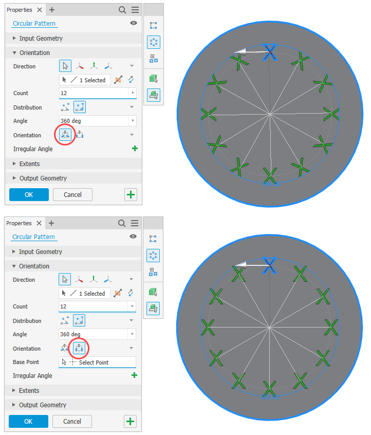
The pattern orientation determines whether the occurrences rotate during the patterning process. Select Rotational when wanting the features to rotate as they move around the axis. Select Fixed when wanting all occurrences to be in the same orientation.
Common Options for Rectangular and Circular
Use Midplane to put the selected components in the middle of the pattern.
Feature patterns are parametric, meaning you can use parameters or link to existing dimensions.
You can use a negative value to pattern in the opposite direction. Yes, it’s the same as flipping, but you could use negatives with parameters to flip the direction.
When patterning a solid, you can attach (Join) the results to the selected body. Or create patterns of multiple individual bodies (New Solid)
Creation Method
With feature patterns, you set the calculation method.
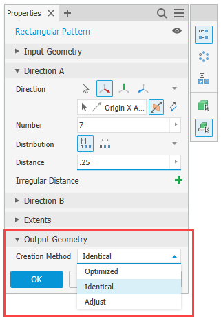
The Optimized method is the quickest, as it copies and reproduces faces instead of features. You will probably use this method the most.
However, there are times when the optimized method fails or produces undesirable results. Then you will want to use Identical. This option creates identical copies of the selected features, copying the collection of features as one blob.
Use Adjust when you need Inventor to recalculate each instance. This is typically the case when each occurrence has a different termination. This option is the least performant option.
Boundaries
The Boundary option lets you fill a selected containment perimeter. Inventor calculates how many instances will populate the boundary. If the boundary changes, the pattern updates automatically to match.
For the boundary, select a face or a (closed-loop) profile that defines it.

Optionally set an Offset. This procedure creates a keepout region between the boundary edge and the offset line. There are three options for patterning inside a boundary:
- Include Geometry—only patterned occurrences completely inside the boundary are included.
- Include Centroids—patterned occurrences completed inside the boundary or with centroids within the boundary are included.
- Base Points—you select the base point for the occurrences. All occurrences with a base point inside the boundary are included.
Be careful using off-angle boundary planes (i.e., ones not parallel to the feature normal). Inventor can produce unpredictable and undesirable results.
When there is no intersection between the boundary plane and the feature, the fully enclosed geometry option is unavailable. It may also produce an error condition.
Irregular Patterns
Starting with Inventor 2026, you can arrange patterns with irregular distances or angles.

Select the green plus (+) in the property panel and select members you wish to vary the distance. You can do this more than once to establish multiple varied distances.
Sketch Driven Patterns
The Sketch Driven Pattern command aligns selected features with points from a sketch. Not really a traditional pattern or array, it gives you control over irregular or non-uniform layouts.
So obviously you need to first create a 2D (or 3D) sketch. In this sketch, add the points where you want each pattern occurrence to be located.

If there are multiple visible sketches, you will need to select the controlling sketch. With the sketch selected, Inventor places an instance at every single point.
Use the Base Point option to select a different occurrence origin.
With Sketch Driven patterns, the orientation is either Fixed or Follow Face. Use Fixed when you want the occurrences to be identical to the original feature. Or use Follow Face for the occurrences to follow the face, adjusting as it goes along the face.
Working with Patterns
Inventor treats all pattern occurrences as one feature. However, it does list individual occurrences under the pattern in the browser. Suppress occurrences to make them invisible. You cannot suppress the base original feature.

Unlike assembly patterns, there is no way to separate an occurrence from the pattern.
Sketch Patterns
I am not going to dive deep into sketch patterns, as they behave like feature patterns. Typically you want to avoid sketch patterns, as feature patterns perform better. You are better off patterning an extrusion than trying to extrude a sketch pattern.

In sketches you can rectangularly and circularly pattern sketch objects. With rectangular patterns, you set the direction, number of instances, and distance between them. Circular patterns array the objects about a selected point, vertex, or work axis. You set the number and angle between occurrences.

You can define boundaries for sketch patterns.
Suppression works a bit differently compared to feature patterns. Opposed to suppressing from the browser, you select instances from the dialog. Instead of making the occurrence invisible, Inventor converts it to construction sketch-only geometry.

In Review
Using feature patterns in Inventor leads to efficiency, accuracy, and design flexibility. Instead of manually creating multiple identical features, you can quickly build a pattern to automate the replication in seconds. Not only is the process quick, but it also creates intelligent, parametric relationships. As your design changes, the pattern updates automatically. Or alter the pattern to account for changes.