 Hi, my name is Paul Munford – writer of Cadsetterout.com and Author of ‘Mastering Inventor surfacing’.
When I first revealed that I was writing a Video tutorial series on surfacing with Inventor, Scott Moyse was one of the first to question Inventor’s surfacing ability. So I thought it right and proper that I should help Scott to quench this rumour – with a guest post on D&M 😉
So what’s a ‘Class A’ surface?
The term ‘Class A’ comes from the automotive clay sculpting rooms of old, and was originally developed as a short hand to help the sculptors know what they should be spending the most care and attention on.
‘Class A’ surfaces can be defined as any surface that has styling intent, which is either seen, touched or both – for instance the body shell of a car.
‘Class B’ refers to those areas that are seen, but rarely – like the inside of the door wells.
‘Class C’ refers to those areas which are never seen or touched, like the underneath of the car.
From Wikipedia:
Class A surfaces is a term used in automotive design to describe a set of freeform surfaces of high efficiency and quality. Although, strictly, it is nothing more than saying the surfaces have curvature and tangency alignment – to ideal aesthetical reflection quality, many people interpret class A surfaces to have G2 (or even G3) curvature continuity to one another.
What’s curvature continuity?
Surface continuity is a way of describing or measuring how smoothly one surface meets another.
G0 = Touching
G1 = Touching + Tangency
G2 = Touching + Tangency + Radius
G3 = Touching + Tangency + Radius + Acceleration
So, can we create G2 or G3 surface continuity with Inventor – sure! However. I’ll admit, although there are tools for maintaining surface continuity in Inventor to G2, there are no tools for maintaining surface continuity to G3.
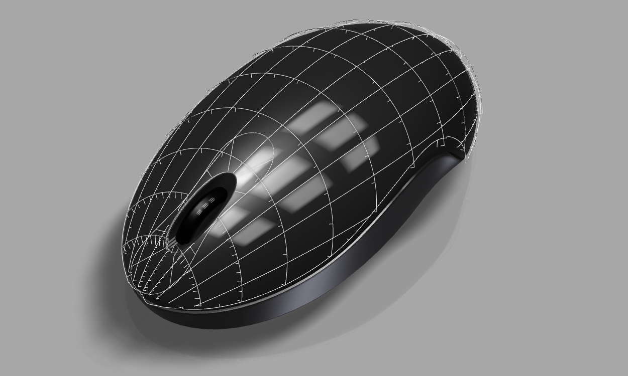
G3 can be achieved, but it is a rather manual process of displaying the curvature comb analysis for a given surface and manually tweaking until it looks about right.
 A 3D mouse model, displaying Autodesk Inventor’s curvature analysis.
Class A accuracy
In recent years the term ‘Class A’ has taken on a new meaning with regard to the accuracy of the computer generated surface.
Here’s some numbers from Andjelic Zoran on GrabCAD:
The distance between each point of the edges of two neighbouring patches [surfaces] must comply with the following limits:
- For class A: no more than 0.01 mm.
- For class B: no more than 0.02 mm.
- For class C: no more than 0.05 mm.
The angle between the tangents to the surface on the edges of two neighbouring patches must comply with the following limits:
- For class A: no more than 6’ (0.1◦)
- For class B: no more than 12’ (0.2◦)
- For class C: no more than 30’ (0.5◦)
So can we achieve this in Inventor? Well, I’m starting to get on shakier ground here. While I’m sure that you could achieve it, I’m not sure how you’d measure it in Inventor, or how you’d report it back!
So – what have we learned?
Can Inventor create ‘Class A’ surfaces? – Yes! Does that make Inventor a ‘Class A’ Surfacing tool? No, sadly not.
Inventor is not going to replace Alias or Catia for those for those of you who create automotive surface models for a living.
There are those of you who work in product or Industrial design who will find that Inventor covers all of your surfacing needs.
In particular, I want those of you who only have access to Inventor to know that you can create great quality surface models. It’s challenging and not entirely painless, but it’s great fun.
You should give it a try.
http://cadso.co/LearnSurfacing
About Paul Munford
 Paul Munford is the CAD/CAM manager at Halstock cabinet makers in the UK. Paul is a contributor to AUGIworld and D3D Magazine, and has been a speaker at Autodesk University for the last three years.
Paul is a firm believer that your CAD software shouldn’t hinder your creativity or productivity and writes awesome tips, tricks and tutorials for AutoCAD and Autodesk Inventor on his blog Cadsetterout.com.


