Back to Civil 3D Design Intent …

In our last article we discussed the methods to insert Civil 3D entities (and general AutoCAD) into Inventor as sketch geometries. Our example used a 2D sketch from a 2D Alignment and a 3D Sketch from a 3D Polyline. These were integrated into a single part file. Now that we have that data, what do we do with it?
We create a design skeleton.
This article will consist of a concept review of skeletal modeling for Civil design, focusing on:
- Establishing our sections along the 2D Alignment
- Projecting the Civil elevation point into each section
- Individual Station components
Orienting our sections along the 2D Alignment
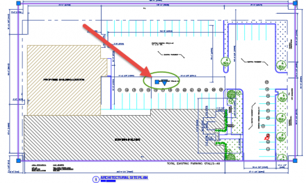
The 2D alignment sketch provides accurate x-y plane geometry to locate our components within the Civil Engineering Design. We want them to drop right into the Civil Engineering Plan with no translation needed. Civil Engineers freak out when things are not related to their coordinate system.
New sketches can now be referenced from the collection of Civil 3D information as follows:
- Creating a new sketch for the Start and End Stations
- Creating a series of sketches along the alignment that define what will be constructed. This would most likely be the skeleton that our components are created upon.
Start and End Stations
The Start and End Stations could have been provided in (and extracted from) the Civil 3D drawing, but would have created a huge problem for us in Inventor. We would have to scrap everything in the event that:
- the slightest stationing changes are dictated by the Civil Engineer
- we decide that the design needs to be adjusted
Taking 5 minutes to orient the Start and End Stations ourselves will permit much greater flexibility.
Our portion of the design will be referenced along the alignment, starting at station 3+15, and ending ….somewhere. The station text and tic marks imported from the Civil 3D DWG give fast and clear visual references to our position along the alignment, as well as geometric constraints to project into our 2D sketch.
Create a 2D sketch on the X-Y plane, and project enough 2D station and alignment information as needed. In the following example I referenced Tic mark for 3+00 to start out from as it is convenient to 3+15. I created 2 lines from the Radius point, one constrained to the projected tic mark, and one dimensionally constrained to the first. An Angular dimension of 4.77 degrees moves the second line to a point on the alignment at 3+15. The equation that determines this will also clear design intent to newcomers.
Here is the equation needed for this :
((360 deg / (Curve_Radius * 2 ul * PI )) * Desired_Length) = Angle deg

Work Planes Along the Alignment
In many cases structures are evenly spaced, and when this holds true, a Circular or Rectangular Pattern can be employed to establish the base planes for a series to construction sketches.
Note: It is best to reference the original Civil 3D sketches where possible, so we will only use the ‘Start End Sketch’ as a reference for the Start and End Work Planes.
- Create the Work Plane for the Start Station (using the Start End Sketch geometries)
- Establish a Work Axis vertically from the curve’s radius point (original 2D sketch and Z axis)
- Pattern the Start Station Work Plane over the sections that are required. (Use the new radius point Work Axis)
Once the Work Planes are in place, we will need to create 2 things at each section:
A 2D sketch for each, and a Work Point along the 3D sketch geometry. Ideally the Work Point should come first, but it is difficult to see which segment along the 3D sketch is the one that relates to each Work Plane. You could do some sketching first, but I will just instruct you to set all the Work Planes to Auto Size. Now we can see our intersections, and can create the 2D sketch in one fluid motion afterward.

Projecting the Civil elevation point into each section
Create a work point at the intersection of each Work Plane, with the segment of the 3D sketch that it crosses. I rename the 3D Point similarly to the others, with its related section.

Now each sketch can be created, and can project the following information:
- The Alignment
- The Work Point associated with this section.
- The X-Y Origin Plane
Now a line can be constrained to the intersection at the 2D alignment, oriented vertically. Next a line drawn horizontally from the projected Work Point will extend until it intersects the vertical line. Create a point at the intersection, and you have the base point for your section’s construction.

This may seem line a lot of work, but considering it only takes about 1-2 minutes per station, that is not much time to get solid 3D information from Civil 3D.
Individual Station components
From here, the remaining sketching can be created for the design, and constrained to the point. In the image below I used a 60’x16’ structure at each section.


All that is needed is to create the Main Assembly, and place in this Skeleton file.
Once all the Structures are added using the skeleton, the design can continue, and eventually be delivered back to the Civil Engineer.
Comments
I think it is obvious that there are some limitations here. First is the act that the method of importation kills any chance of dynamic update within the Civil 3D information. Secondly, once any Section Work Plane moves beyond a segment due to adjustment, the Work Point will need to be redefined.
In the interim, until Autodesk grants my request to step up this interoperability with dynamic updates, the best we could do is to create fluid 3D geometry over the segmented Civil 3D 3D Poly line to create more adjustable sections.
Check back and we will move forward and review how Fusion will take this Assembly and prepare it for the AutoCAD environment.
Check out “Fusion – Bridging the Gap Between Inventor and Civil 3D”