The AutoCAD Region command is a special kind of 2D object that has physical properties like centroid and moment of inertia that can be calculated using MASSPROP command. These geometries can also be converted into complex geometries with the help of Boolean operations Union, subtract and Intersect.
AutoCAD Regions can be created using closed objects with line, polyline, circle, arc, revision cloud, ellipse or spline. To create a Region, select the Region tool from the expanded Home tab on the Draw panel, then select all geometries forming a closed loop with which you want to create the region and press enter.
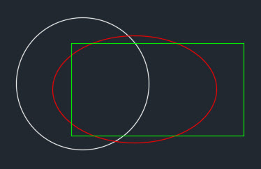
In a similar way you can create multiple regions for performing Boolean operations. To explain the Boolean operation with a region, I will use three regions created with a circle, rectangle and ellipse as shown in image below.
Union:
Using Union command you can merge all regions into a single unit in such a way that only extreme boundaries of all regions are retained and all internal boundaries are merged. To use this command type UNION at the command line, press enter, then select all three regions from drawing area and press enter again. The final region will look like this.

Subtract:
Using the subtract command you can remove an overlapping part of one region from another. To use this command type SUBTRACT at the command line and press enter, then select the region from which you want to remove the geometries. In this case I am selecting the circle as my primary region, after selecting circle press enter, then select the ellipse and rectangle regions, ending by pressing enter again. In this case overlapping parts of the rectangle and ellipse are removed from the circular region giving it a shape which looks like geometry shown below.

Intersect:
Intersect command will create a region that comprises of only the common regions of all meshing geometries. To use this command type INTERSECT at the command line and press enter, then select all of the regions in the drawing area and press enter again. You will get combined geometry which looks like the image shown below. You can clearly see that in this case only the common area of all these three regions is retained.

More about AutoCAD Regions:
When a region is created with 2D geometries, the geometries are deleted and the region is created. But if you want to retain the geometry as well as the region, then change value of system variable DELOBJ to 0. By changing the system variable you will force AutoCAD to create a region retaining the 2D geometry with which it was made.
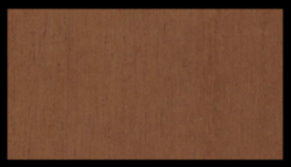
You can even apply materials to the region, just like a 3D solid or surface entity. In the image below I have applied Mahogany Natural Low Gloss wooden material to the rectangular region and then rendered it.
About the Author:
Jaiprakash Pandey is CAD Corporate Trainer specializing in AutoCAD, CATIA and other CAD software’s. He is an Autodesk AutoCAD Certified professional and an Autodesk expert elite. He is a regular contributor to AUGI World magazine and he has also developed AutoCAD video courses for pluralsight, his own platform SourceCAD and other E-Learning businesses. For free AutoCAD tutorials by him visit SourceCAD.


