K-factor; what is it, and why does it matter to me? Design & Motion is all about digital prototyping. For digital prototypes to be most effective, what we produce digitally (in the form of models and drawings) needs to represent the finished product as closely as possible. In my experience, the area of manufacturing where this need for accuracy seems to be most neglected, is in sheet metal design. For applications where sheet metal components do require tight dimensional tolerances, too often I hear the blame game where the fabricator tells me the designer always gets the blanks wrong, and the designer tells me that the fabricator can’t fold his parts accurately. In a lot of these situations, neither the fabricator nor the designer has a good understanding of where the error comes from.

With modern CAD tools, the ability to unfold a complex sheet metal shape to produce a blank is all too easy. The problem with it, is because the blank looks correct, many designers assume that it is, without taking into account the fact that software has been set with a default value that is used to calculate how the material changes in length when it is folded. The folded component will only be dimensionally correct if the blank is also correct. There are many methods for quantifying the amount of material to allow for a fold, but in my opinion, the easiest and most efficient one to use relates to a magic number called K-factor.
You’ll remember from Mechanics 101, that when a material is placed in a “bending” scenario, the top surface of the material goes into compression, and the bottom surface is stressed under tension. Between the two extreme surfaces, there is a gradual change from compression to tension, with a plane right in the centre that is neither in tension or compression. This is often called the neutral axis. When we take this bending to the extreme and actually push the material beyond elastic limit, like we do when folding sheet metal, the plane that is under the least amount of stress is not actually always in the center of the thickness of the material. Exactly where it lies depends on a number of factors such as the type of material, how “tightly” you are folding it etc. For any given bending scenario, the neutral axis of the material will lie somewhere between the inner surface of the bend and exactly half of the thickness of the material. We can quantify exactly where it lies by expressing it as a percentage of the thickness of the material. We call this the K-factor. So for a very large radius bend where the neutral axis lies right in the center of the material, the K-factor would be exactly 0.5, or half the thickness.

Most CAD systems that have sheet metal design tools will allow you to input a K-factor that the software uses to calculate the unfolding to give an accurate blank, or flat pattern. This is all well and good, but how do you know what K-factor to put into the software? Well the easiest and best way to do this, is to perform a bend test for a particular scenario, and then back-calculate the K-factor from measurement data. To make this easier, we have come up with a handy K-factor calculator for you to use. Just follow these simple steps and it will spit out a K-factor for you to input into your CAD tool.

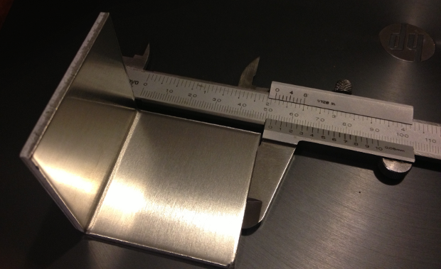
1. Cut a blank to a specific length (say 100mm) and measure it as accurately as possible.
2. Mark a fold line exactly in the center.
3. Configure the press or other folding tool with your desired tooling and make a 90 degree fold on the bend line.
4. Measure the outside lengths of both legs of the fold and input them into the calculator as well as the inside bend radius (this can be measured with a radius gauge.)
5. The calculator will give you the K-factor. Make sure you record the details of the tooling used, material thickness, and material type that correspond with this particular K-factor.

If this method is used, you will find that your CAD software will produce incredibly accurate blanks and your folded components should turn out spot on.
For Autodesk Inventor users, I recommend that you set up multiple sheet metal styles for each bending scenario and name them to include the tooling and material details (eg 1.5mm Aluminium – 16mm Vee) and set the K-factor for each one after performing a bend test and calculation. This way, when you create a new part, you can simply select the style that you want and know that your K-factor is set correctly.
Here’s to accurate blanks!
update:
Multi-body sheet metal enhancements in Autodesk Inventor 2016


