
As I took a deep dive into Inventor’s assembly mirror capabilities, I’d be remiss to not also discuss Inventor Patterns.
Autodesk Inventor’s patterning tools allow you to duplicate sketch objects, part features, and components in assemblies in an ordered arrangement. You can pattern in different layouts, such as a rectangular grid, a circular array around an axis, and along a path. This process can save significant time in both the creation and the modification of your designs.
Inventor Patterns: Assembly
With assemblies, you can pattern parts and subassemblies. After selecting the components, select the patterning type. Inventor provides three assembly patterning options.
Rectangular and Circular create non-associative, independent arrays. You define the directions, spacing, and number of instances.
Hot Tip: position and constrain the source component. If it moves, the entire pattern moves with it.
Rectangular Assembly Patterns
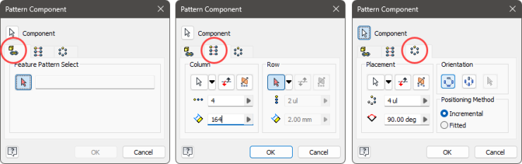
The Rectangular layout arranges the selected components into repeating columns and rows.
You must specify at least one direction. The direction aligns the row or column along a selected axis or model edge. You can also select an origin axis from the menu.
With only one direction, you get a single linear row pattern. In two directions, you obtain a rectangular array with multiple rows and columns.
With the components and direction(s) selected, set the number of occurrences (i.e., how many instances are in the pattern) and the spacing between them. Spacing is the distance from the start of one instance to the next, not the distance between instances. It is parametric, meaning you can use parameters or link to existing dimensions. The count must be greater than zero.
Use Flip to reverse the direction of the column or row. Alternatively, you can specify a negative spacing, which also reverses the direction.
Use Midplane to put the selected components in the middle of the pattern.
Circular Assembly Patterns
Like rectangular, you start by selecting the components. Opposed to the direction, you specify the axis of rotation. This is the point that the components pattern about. You can select an edge, work axis, cylindrical face, or select an origin axis from the menu.
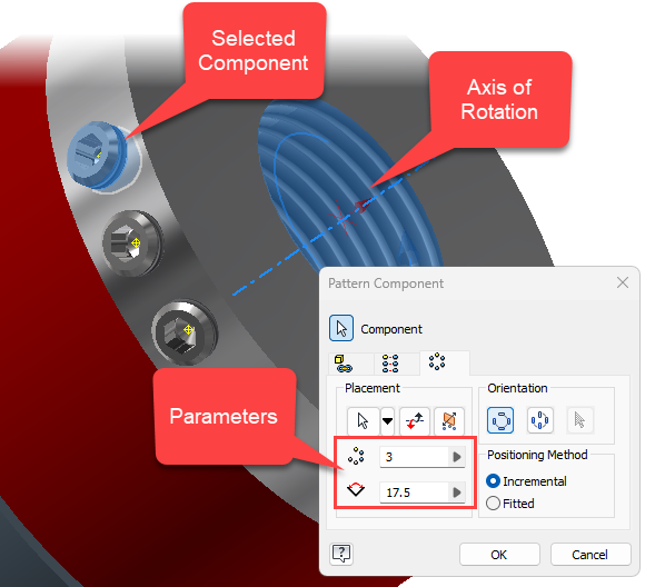
You then specify the count, which must be greater than zero, and the angle to fill—the angular distance between occurrences. Flip reverses direction from counterclockwise to clockwise.
When the positioning method is set to incremental, the spacing becomes the angular distance between occurrences. When fitted, the distance represents the total angle, and Inventor calculates the angular distance between occurrences.
Use Midplane to center the pattern around selected components and create a pattern in two directions from them.
The pattern orientation manages how or if the occurrences rotate as the pattern moves about the rotational axis. Select Rotational when wanting the components to rotate as it moves around the axis. Select Fixed when wanting all occurrences to be in the same orientation.
Consider the numbers on a clock face. Do you want all the numbers to be vertical (fixed) or rotate (rotational) as you go around the clock?
With Fixed optionally also set a base point to redefine the pattern’s base point.
Associative Inventor Patterns
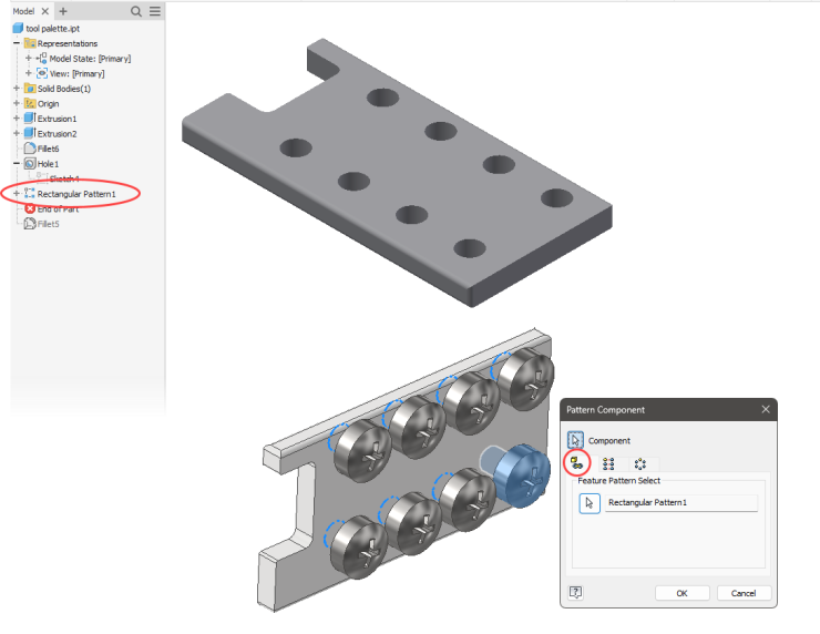
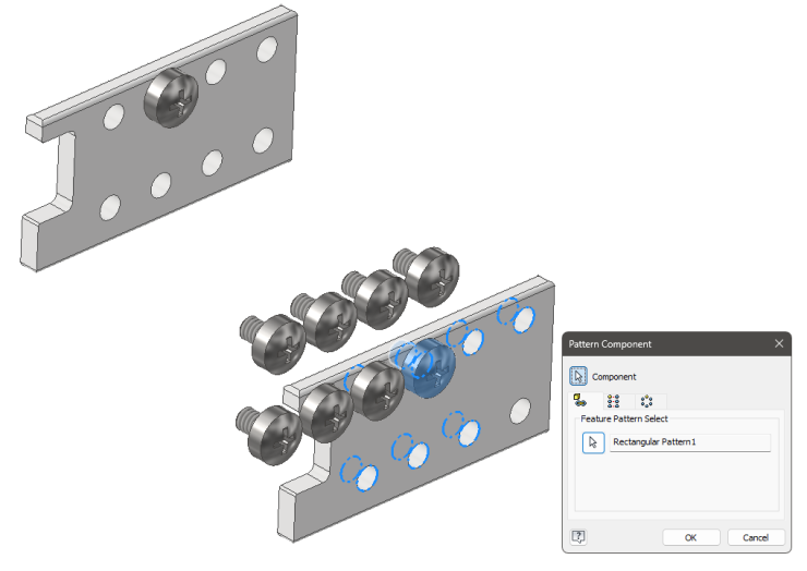
The associative assembly feature duplicates the selected components, arranging them to match an existing part’s feature pattern. This creates an associative link. If you modify the original part’s feature pattern, the corresponding assembly pattern updates automatically. With this option, you have no directions to select, counts to manage, or distances to set.
The assembly pattern updates with changes to the feature pattern.
It is important to position the source component at the source feature of the part pattern. Inventor only uses the part’s pattern for direction and spacing. In this example, I have positioned the initial fastener at a hole occurrence amongst the part’s feature pattern. The resultant assembly pattern has the correct spacing and direction, but the location is incorrect.
Working with the Inventor Pattern
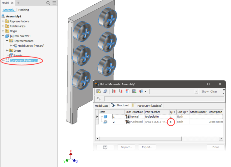
First thing of note is that patterned components count toward the bill of materials. As the pattern changes in count, so does the quantity in the BOM update to match.
Deleting a pattern removes all occurrences but leaves the original components.
Patterned elements are listed in the browser under an assembly pattern icon.
Expand this to see each instance and interact with it like any other component in the assembly. You will find most features in the right-click menu. For example, you can turn its visibility on or off. Applicable changes will be captured by the view representation or model state.
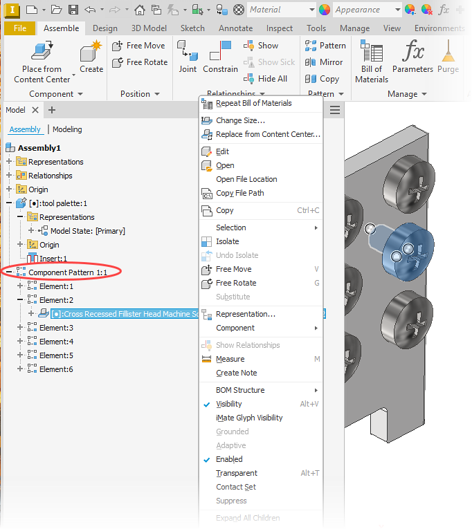
You can also work with the pattern occurrences (via the right-click menu).
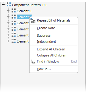
Suppress individual occurrences to turn them off and exclude them from the pattern. Suppressing an occurrence also updates the BOM quantity. The browser icon updates to reflect the suppressed occurrence.
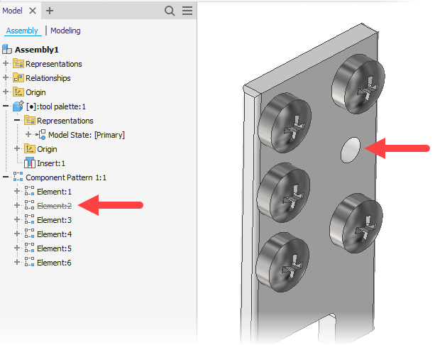
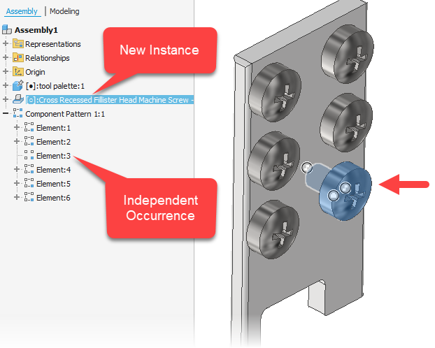
Making an occurrence Independent severs its link to the pattern. The instance is removed from the pattern, adjusting its count, and allows you to move and position the component independently from the pattern.
What is actually happening? Inventor suppresses the pattern’s occurrence and inserts a new copy. The new instance is placed in the same position and orientation as the suppressed element. The new instance appears above the pattern’s browser node. The occurrence’s browser icon changes (very slightly) to indicate the broken link.
Now something unexpected happens when turning off independence. Remember, Inventor did a slight of hand and inserted a new component while suppressing the pattern’s occurrence. So when turning off independence, Inventor unsuppresses the pattern’s occurrence but does not remove the copied component.
Be careful with this. If you had not moved the copied instance, the restored occurrence would be right on top of it. You might end up with an unexpected duplicate!
Other Assembly Features that Pattern
Pattern Component is only one of Inventor’s assembly features that will pattern components.
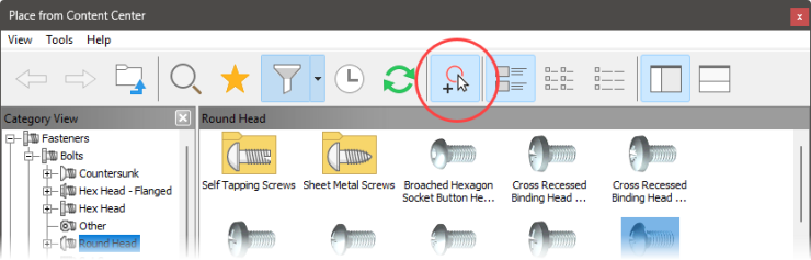
Place from Content Center
I’m not going to dive into how to use the Content Center but want to highlight two AutoDrop options that will insert multiple instances. With AutoDrop, Inventor automatically sizes, places, and constrains standard content (like bolts).
After locating the instance, you can enable features on the AutoDrop toolbar. Like Follow Pattern.
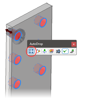
With Follow Pattern, the AutoDrop follows a found feature pattern. It does not matter the type of feature pattern. Unlike the Pattern Component command, it does not matter where you place the first instance; Inventor patterns it correctly.
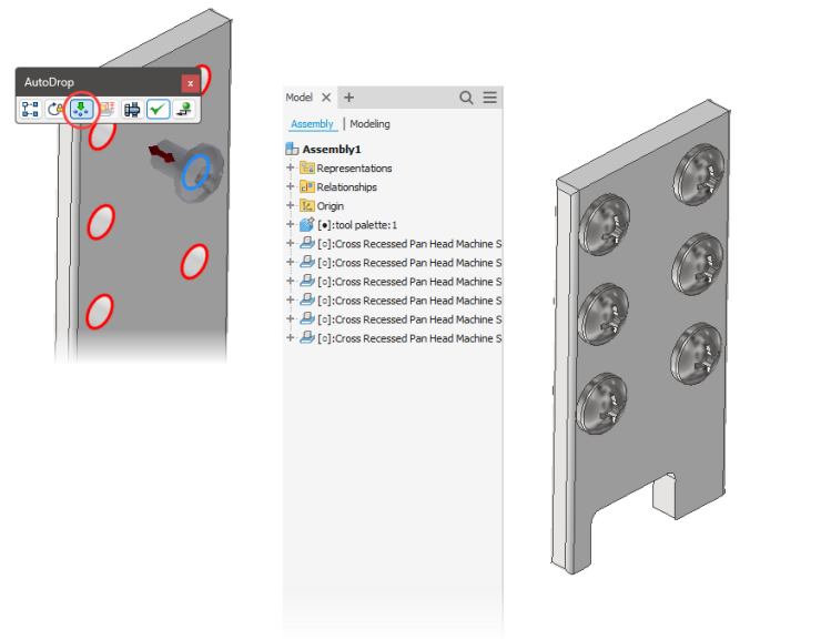
Insert Multiple does not rely on feature patterns. Instead, if Inventor locates “available targets,” it inserts an instance at each one. This results in multiple independent instances, not a pattern. It is also smart enough to ignore targets already occupied.
Bolted Connection Wizard
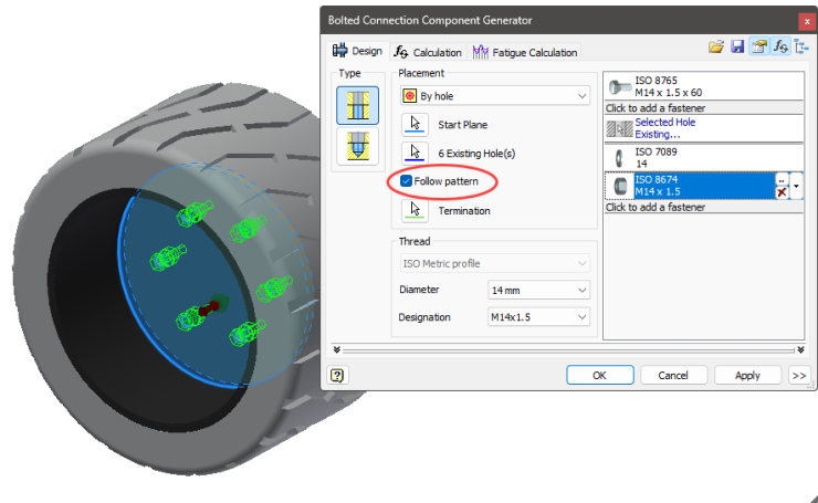
The Bolted Connection Component Generator allows you to quickly insert everything needed for a bolted connection. This includes the fastener, related components, and the holes.
When placing a connection with the By Hole option, enable Follow pattern to get the Bolted Connection Generator to recognize existing feature patterns. It then inserts the connection into each patterned hole. It will only allow you to select the initial feature, so no worries about misplacing the pattern.
And here’s a patterns live and in action…
Feature Image by Alex Perez on Unsplash


