In this article, I’ll explore a workflow for utilising the Limits / Fits tools in Inventor, to maximise the benefits of using an integrated CAM system for precision machining. To start off with though, I’m going to explain a bit about Limits / Fits for the uninitiated.

When a particular design calls for a precise fit between two components, every engineer I know usually pulls out his/her copy of Machinery’s Handbook (or Boundy) and looks up the table of Limits/Fits. Inventor has these fits built in, so as long as you know what you’re looking for, it will put the correct tolerance limits on dimensions in the drawing environment, for you, once you have specified the appropriate fit. A slightly lesser known feature, is that tolerances can be used in the modelling environment as well. These model dimensions can then be retrieved and placed on the drawing.
Limits / Fits
For those of you who may not have dealt with Limits / Fits in a CAD environment, you typically dimension the part with a nominal dimension, and then specify a tolerance by listing upper and lower limits for the specified quantity. This allows the machinist a range to work within, that ensure the correct clearance or interference between the two components, regardless of whether he/she is at the upper or lower limit.
The limits/fits that everyone uses today, were conceived a long while ago, by clever people who are now probably long dead. Their age doesn’t make them any less useful today.
Broad fits categories
- Clearance – There is always a gap between the 2 components, regardless of whether each part sits at it’s upper or lower size limits.
- Transitional – Depending on where each part sits between upper and lower limits, there may be a gap between the two components, they may be identical in size, or material may even need to be deformed/displaced to fit them together.
- Interference – There is always material required to be deformed or displaced in order to get the parts to fit together.
Within those categories, sub-categories of fits are often described using descriptive names such as “Loose-Running,” “Close-Running,” or “Sliding.”
You can choose to base the fit on either the hole or the shaft, and the codes for the fit are either upper or lower case to designate this.
Now obviously, if you have a range of possible sizes for the shaft, and a range of possible sizes for the hole, then there are an infinite number of permutations between the extremes. To deal with this, we often just look at the best and worst case scenarios and decide if they are suitable.
If the hole diameter is at the upper limit, then the component (with the hole in it) has less material than one with the hole diameter at the lower limit. In other words, a bigger hole removes more material. Conversely, a shaft whose diameter is at the upper limit has more material, than one whose diameter is at the lower limit.
So we have two combinations which form the extremes of the fit between these two components. The first is the biggest possible shaft in the smallest possible hole, and the second is the smallest possible shaft in the biggest possible hole. In a clearance fit scenario, they give the smallest possible clearance, and largest possible clearance respectively. We call the first scenario the “maximum material condition,” and the second, the “minimum material condition.”
Example:
If we have, say, a pin that needs to fit into a boss, but slide in a smooth fashion and remain co-axial to a high degree of accuracy, we may choose a Close Running fit. This has corresponding codes of H8/f7 in the hole basis system, and f8/H7 in the shaft basis system.
We’ll be using the hole-basis system, which means that the nominal size lies on the lower limit of the hole diameter. Another way to think about this, is if we have a perfect hole, exactly at the nominal diameter, then we will have to remove material from the shaft to get a clearance fit.
Hole:
The nominal diameter is 50mm, and the H8 limits for that size give a range of 50.000mm to 50.039mm. This means that if the finished part comes out anywhere between these values, we would consider it a “pass” and it will give the desired fit when the shaft is inserted into the hole, as long as that is within it’s acceptable range too.
Shaft:
The nominal diameter is 50mm, and the f7 limits for that size give a range of 49.975mm to 49.950mm.
So when the parts are assembled, you can see that there could be a maximum clearance between them of 0.089mm, and a minimum of 0.025mm, depending on where the individual components sit within their tolerance range.
So how do we represent this information in our CAD model, and how do we go about conveying this information to the machinist you ask? Good question, I’m glad you asked….
Well, the way it has generally been done for as long as I know of, is that components are usually modelled or drawn at the nominal size. Tolerance notes are then added to the dimensions on the drawing, to show the machinist the acceptable range for dimensions of the finished component.
 An example of a nominal diameter dimension with a fit code, and size limits
This is all well and good if the machinist is making this component by hand, and can adjust the size to suit, but what if we want to control a CNC machine using the modelled part? We can’t just toolpath everything at exact size, otherwise fits won’t work. Sometimes CNC operators adjust the offset parameters in the machine control to cut slightly bigger or smaller, but this is not a very good way to manage things. Even worse is hand-editing the machine code, as it gives opportunity for error and is slow.
A skilled machinist can definitely achieve very high accuracy on manual machines, but usually it is a case of removing material until close to size, and then taking a series of small cuts, with measurements in between, until the finished size is reached.
With CNC machines, this is not an easy or efficient process to use, as you have to wait for the program to complete, then create new code or make adjustments, before starting a program again. A much nicer way to work, is to have a good program, that you know will produce a part of the required dimensions.
So how do we create a model that can be toolpathed to give exactly the required result?
This is where the fun stuff starts. In Inventor, when you specify a value for a parameter, you can click the little arrow to the right side of the input box and select “Tolerance.” This will bring up a dialog that allows you to add tolerance information to the parameter.
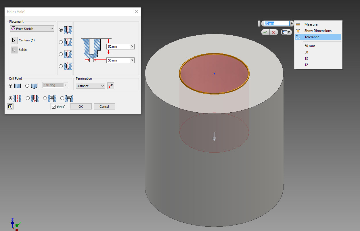 The tolerance settings for an Inventor Parameter
By changing the “Evaluated Size” you can change where in the tolerance range, the actual model sits. You have 4 options, shown below.
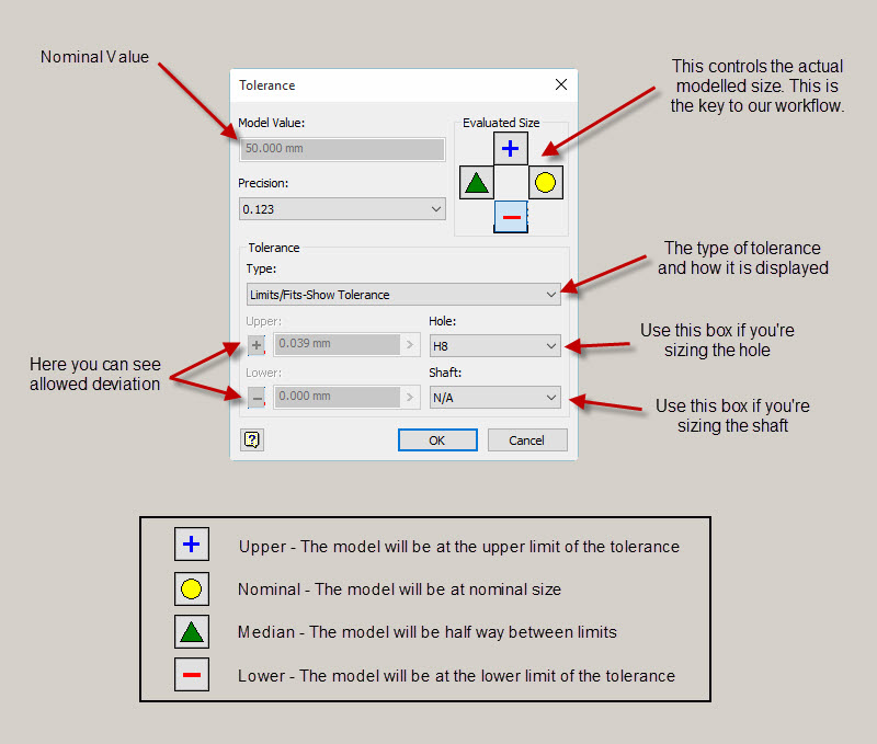 The tolerance dialog – What the various options do
So you can have the model represent either the maximum material condition, minimum material condition, nominal size, or half way between upper and lower limits. This gives a great deal of flexibility for use in the CAM environment (Inventor HSM), but also for visualising the fits, which I’ll show in more detail below.
When creating the CAM program, the software uses the actual geometry of the solid, to calculate the toolpaths. If you model it at the nominal diameter, then the CNC machine will machine it to close to the nominal diameter. I say close because all machines have some degree of error.
If however, you pick a tolerance that is at least twice the known potential machine error, then by selecting the “Median” value for the “Evaluated Size” option in the tolerance box, your finished part should end up within tolerance, because the toolpath will be calculated on the median value.
To illustrate what I mean, have a look at shaft diameter in the model, with each of the “Evaluated Size” settings selected:
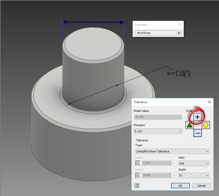 Upper Limit (Click to zoom) Upper Limit (Click to zoom) |
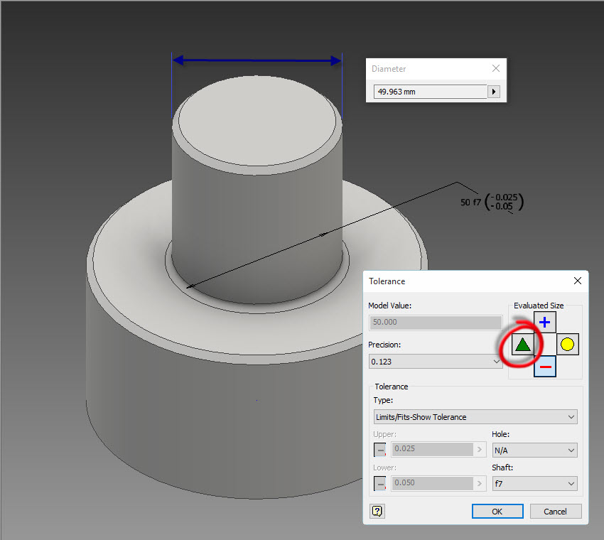 Median (Click to zoom) Median (Click to zoom) |
 Lower Limit (Click to zoom) Lower Limit (Click to zoom) |
Proving it out
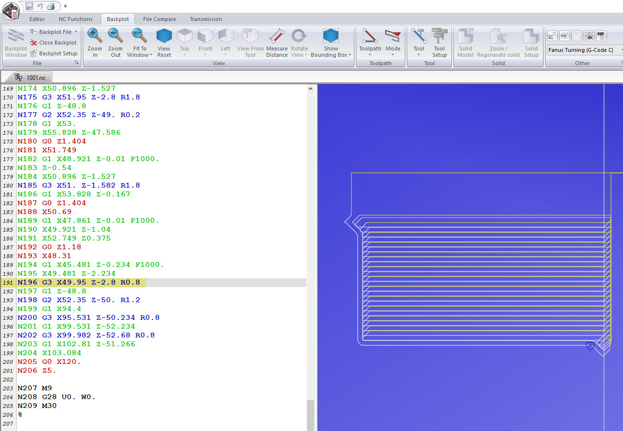
To prove it out, I created the following turning toolpath in HSM, with the “Evaluated Size” option in the model set to “Lower Limit.”
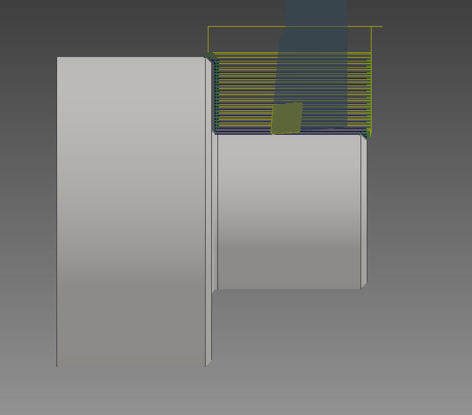
I then posted the code and inspected the X-axis coordinate of the final cutting pass (i.e. the finished diameter.)
I hope this has given you some ideas for utilising the Inventor tolerance capabilities in a machining context. I think it’s a really neat way to keep the manufacturing information inside the CAD model, and helps to create a richer digital representation of the component that is being manufactured.
Until next time…


