I was reminded about Corridor Assembly Interval frequencies. There are numerous ways to adjust these settings, so I thought a fast review of these seemed like a good topic.
A Corridor is broken into Baselines and Baselines into subsequent Regions. Each region carries it’s own independent settings for various things including how often an Assembly is positioned along the Alignment. These settings are broken down further into Linear, Curved, and Spiral segments. The default settings are often every 25’ for all types.
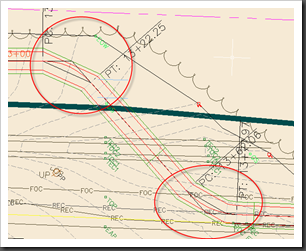
This is fine for many linear applications where grade changes are consistent. However, as you an see in the example below, curved applications lack enough interval frequency to be accurate or useful.
In the example above, the curved portions of the Corridor are segmented at 25’ intervals. As is true in many fine detailed situations, a 25’ interval is too sparse to accurately grade the region. So we should change this region’s interval frequency in the Corridor properties to something more useful.
We’ll look at the 4 settings that apply to this kind of adjustment:
- By Region
- By Baseline
- By Corridor
- By Command Settings
Corridor Properties and Regions
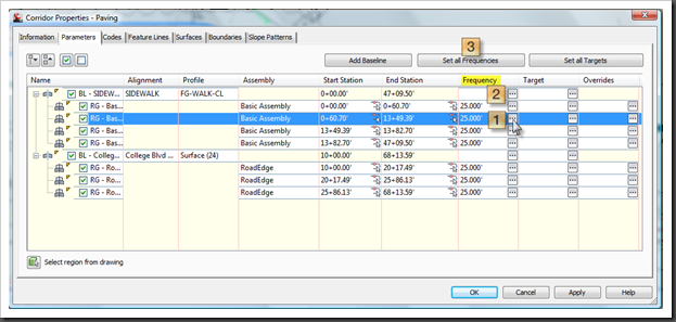
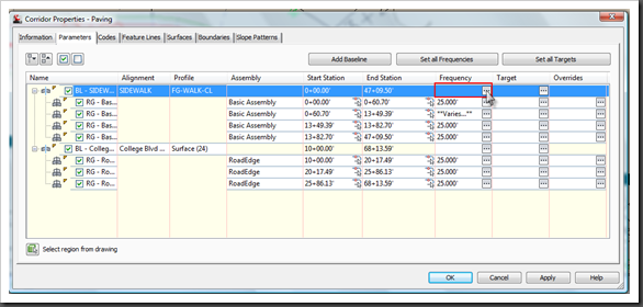
In the image below we see 25.000’ in the frequency field of each region, indicating that all segment types for each Region are set to 25’. If we select the frequency button for a specific region, that region’s property dialog will appear.
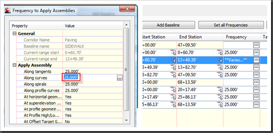
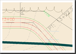
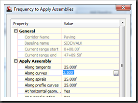
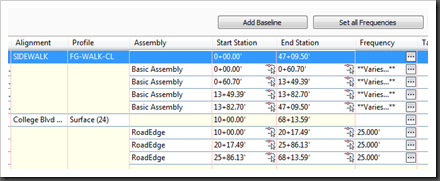
We change the 25’ to 2.5’ in the ‘Along Curves’ field. After it updates the region, the display changes to “Varies”. (Tangent, Spirals, and Profile curves are still set to 25’). If we go back to the Corridor model, we’ll see the curve updated with Assemblies at every 2.5 ‘.
What happens when we need to change all curves through an entire baseline? We’d want to take a different route.
Frequency Header and Baselines
That’s where the Frequency header comes in. Picking it will give you global reach over the entire station range in any particular baseline. In the example below, the frequency interval is being selected for the entire baseline of the Sidewalk.
Once changed in the Baseline header, the entire baseline will update accordingly.
Entire Corridor
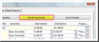
Making the changes to the entire Corridor is even easier, and more obvious. Just hit the big button at the top of the dialog.
Corridor Alterations
If we split any regions thereafter, the existing setting will be transferred from the original region to the 2 split regions. Notice I said SPLIT. In the event that a region is ADDED to a Corridor, then it’s a NEW region and will adopt it’s properties from the Command Settings.
Command Settings
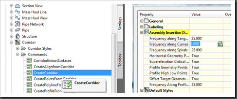
Any new Corridor is subject to the default Command settings. There are no settings for a new region, so the settings are derived from he next best thing, a new Corridor. Navigate to the Corridor command settings and double click:
Toolspace -> Settings Tab –> Corridor –> Create Corridor
Here most of the default settings that pertain to creating a new Corridor are catalogued. Under the Assembly Insertion Defaults you will find our Assembly Frequency Intervals. I adjusted mine to 5’, so we can see the difference after we return to the Corridor Properties (the last change we made was 2.5’).
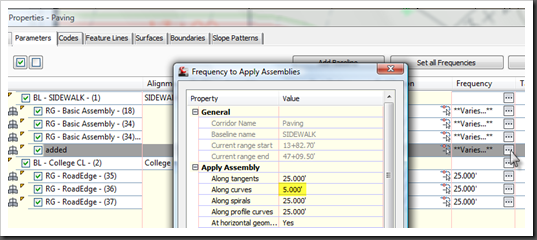
After retuning to the Corridor Properties, I added a region after the last in the sidewalk baseline. Upon opening the frequency dialog for that new region we see is set to 5’.
Comments
These settings are very useful:
- When grades become erratic in an area
- When in horizontal or vertical curves
- When ever more definition of model and daylighting is required
There are a few things to consider when adjusting Assembly frequencies. Memory use, speed, and performance. This kind of alteration can get messy and really slow to rebuild. If for example you save the frequency of a 10 mile long road at 1’ intervals, you might be opening a backup next time. Just be sensible, and don’t use more frequency than you need. Excess is inefficient.
Many groups only use to Corridor for it’s model and surface functionality, leaving any other visual references to ‘pretty’ 2D drafted geometry. In the event that you choose to maximize the Corridor for more of it’s material and Feature Line visualizations, you will need to increase the the curve and spiral frequencies dramatically, possibly sub 1’, depending on viewed scale.
That is all there is to it. Knowing which location to globally effect you desired settings should save some hassle and frustration. The best advice I can give is to set your default common Corridor properties in the Command settings and save that in your Standard Template for future designs.

