
CAM/CNC 101 – The software side:
For those that have never had any exposure to CAM (computer aided manufacturing) and CNC (computer numerical control), the principles of it are as follows. A 2D or 3D software representation (model or drawing) of a component is interpreted by some clever algorithms in conjunction with some user input inside a piece of software known as a CAM application. These algorithms generate paths in 3D space for a cutting tool to follow.
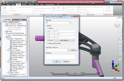
 3D T-Splines Freeform CAM Model in Autodesk InventorHSM 2015
Once these paths have been generated, another piece of software called a post-processor converts the paths into another form of code which can be read by a controller built into the CNC machine. This is often of a format known as G-code. There are a huge range of standard G-codes which define different types of movement on the machine. For further detail, see Wikipedia G-Code definition.
Controllers and Software:
I’m going to skip over the CAM step for now, as this is a huge topic on it’s own. I use the Autodesk HSM (high-speed machining) solutions for all my CAM work and I’ll follow up with a post on InventorHSM soon.
In a commercial CNC machine, the controller is usually a self-contained unit with a control panel (see an example from Haas below), that the machine operator stands in front of and has the ability to have control code inputted directly from the panel, or be “piped” to the machine from a computer with CAM software (known as DNC).
 A Haas CNC controller attached to a Haas Vertical Machining Center (3 axis Mill)
For hobbyists, or others on limited budgets, these controllers are very expensive, but other options exist. A common route is to emulate the machine controller with a software based solution that uses a normal keyboard and mouse for input and a computer monitor for visual feedback. There are quite a few options here, but the popular ones are LinuxCNC (formally EMC) and Mach3 (Windows based.) LinuxCNC is a free open-source solution, while Mach 3 is a commercial product. A few years ago, having had a look at both, I decided to give LinuxCNC a go given that it was free, and found it to be brilliant.
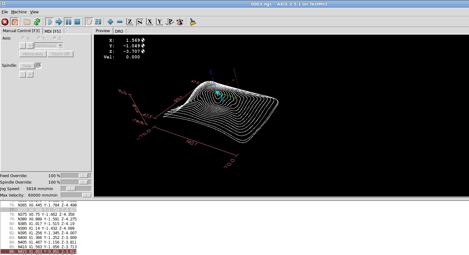 LinuxCNC Machine Controller with NC Program Loaded
The flexibility that these controllers provide are amazing. LinuxCNC supports up to 9 axes of motions and has support for various kinematics systems, including robotic arms. I have seen examples of LinuxCNC running hexapod robotic spiders. And this is a free open-source package! To use it, once configured, you simply load your NC code file, review the toolpaths in the preview, check that your tools are in order and hit the Start button. The motors whizz into life and the cutter starts to make chips fly. All going well, you end up with a finished part.
Calibration / Tuning:
To get LinuxCNC to work with any machine, there is a process of set up and calibration that has to be performed. With an enormous variety of motor types, PC specifications, sensors and switches that all provide inputs and outputs for LinuxCNC, you can imagine that hardly any 2 setups are identical. Luckily, the calibration and tuning process for the motors is fairly straightforward. You may remember from Part 1: The Mechanical Conversion, that we calculated the distance that each axis would move for each “step” that the controller sent to the motor. That data needs to be fed into LinuxCNC so that the software knows how many steps to send to the motors, to move the cutter to the correct position.
 Stepper Motor Configuration in LinuxCNC Step Configuration Wizard
Step Configuration Wizard in LinuxCNC provides a really simple way to input the required information. After setting up the motors, limit switches, emergency stops and other I/O can be configured with a straightforward pin map for the motor controller. I used a Geckodrive G540 which has preset options installed in LinuxCNC by default. In Part 2: The Electronics, I talk more about the role of the Geckodrive G540.
With all of this set up, the next step was to test the 3 axes and adjust the tuning to get the motors running really smoothly. A trimpot for each of the axes is provided on the G540 stepper driver that allows fine motor tuning. It’s simply a matter of running each axis and turning the screw backwards and forwards until an audible “sweet spot” is heard. Following this, accuracy checks needed to be performed. There are many ways to achieve this, but the process is basically about checking that the machined dimensions of a real component match the modelled dimensions as closely as possible. I often use drilled holes to check this. I drill a hole at one end of a piece of material, and then move a fixed amount in one direction and drill a second hole. Next I measure the center distance between the holes and compare with the commanded distance. Finally I move the axis back in the opposite direction and measure the error between the two. Repeating this a number of times and averaging the error gives me the backlash in an axis.
 Leadscrews modelled and rendered by Sherwin Perez, as posted on GrabCAD
Backlash is basically the amount of “slop” in a mechanical system when changing direction, due to clearance in transmission of drive or other “looseness.” There is usually some backlash in any system, and the goal is to reduce it to as much as possible. The remaining amount can usually then be dealt with with software backlash compensation. The way this works, is that you program a known amount of backlash into the machine controller, and the machine compensates for this amount every time the motors reverse direction. This is surprisingly effective. My mill has approximately 0.3mm of backlash in the x-axis, and with backlash compensation in LinuxCNC set up, the resulting backlash error in the part is closer to 0.05mm. Most of my backlash is due to trapezoidal thread leadscrews that drive the 3 axes. I am in the process of designing a conversion to replace the lead screws with much more accurate ballscrews that have close to zero backlash. I’ll make sure to write an update post to cover this.
 Ballscrew modelled and rendered by Giacomo Calzoni, as posted on GrabCAD
In my next post in this series, I’ll cover the first parts that I machined and the issues with software step generation. I’ll also talk about how I overcame this issue and the dramatic improvement in performance that was achieved through the use of a $180 bit of hardware.
’til next time….
[subscribe2]

