
What’s New in SOLIDWORKS 2017 Parts Environment?
The new SOLIDWORKS is here! 2017 is upon us with a slew of updates providing “the power you need to drive innovation.”
Sketching
Sketching provides the foundation for most of your part models. Yet, sketching can feel like one of those necessary evils at times as it can be tedious and lacks a lot of the glamor of the 3D side of modeling. With that in mind, SOLIDWORKS 2017 makes it easier to work with existing geometry. Here’s what’s new with sketching:
- Creating Sketch Offsets on 3D Geometry Surfaces
- Enhancements to the Segment Tool
- Prevention of Accidental Micro Lines
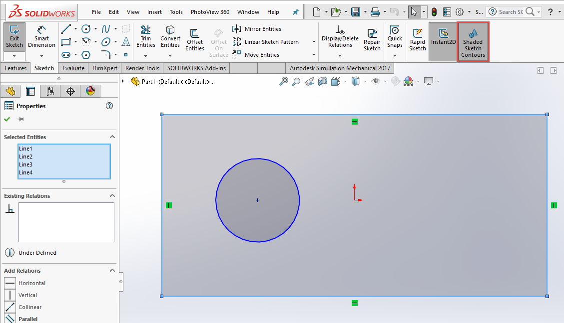
- Shaded Sketch Contours
Use Offset on Surface to quickly generate a 3D Sketch with geometry offset from the edges of a selected face.

The Segment tool in 2016 only worked with circles and arcs. The Segment tool within SOLIDWORKS 2017 is expanded to work with splines, parabolas, ellipses, and conics.
With Shade Sketch Contours, closed loops within the sketch appear shaded. This makes it clearly obvious what is ready to be converted to 3D. Other special things are possible now, like moving the sketch by clicking-and-dragging the shaded area.
Part Modeling
The Part Modeling updates made the Top 10 New Features in SOLIDWORKS 2017. The enhancements described as “More Powerful Modeling Tools,” mean faster, easier
modeling with fewer picks and clicks. Here is the list of what’s new:
- Advanced Holes
- Bidirectional Circular Patterns
- Chamfer Enhancement
- Converting Features to Bodies and Surfaces
- Cut List Sorting
- Derived Part References are Retained
- Disabling and Enabling Equations in All Configurations
- Extrude from Any Size Planar Face
- Rebuilding All Configurations
- Running FeatureWorks After Adding Items to Imported Parts
- Select All for Split Features and Save Bodies
- Sweep Profile Selection of Faces, Edges, and Curves
- Thread Enhancements
- What’s Wrong Enhancements
- Window Selection for Instances to Skip
- Wrap Creates Geometry on Any Face
- Creating Three Bend Corner Reliefs
- Normal Cuts
- Punch Table Support for Mirrored and Derived Parts
- Sheet Metal Options
The new Advanced Hole tool allows you to build-up your own custom hole configurations and the reuse it in any model.

Circular Patterns are no longer limited by only patterning in one direction. New symmetrical and asymmetrical options mean the pattern can grow in two directions from the original feature.

Chamfer meet Fillet, Fillet this is chamfer. The Chamfer feature has been updated to align with the Fillet feature including options for Offset Face and Face Face features.

Chamfers can be quickly flipped to Fillets and Fillets quickly flipped to Chamfers…. Boom!

You can create boss, cut, and surface extrudes from any size surface, face, or plane. Previously the From selection needed to encapsulate the entire sketch.
Faces and Edges can now be directly selected to use as sweep profiles, without the step of creating a sketch with converted entities.
The thread feature includes a couple kick-ass updates: Trimmed Threads and Multiple Starts.

What’s Wrong details now appear with the FeatureManager, breadcrumbs, and graphic area meaning they are no longer just limited to the What’s Wrong dialog… this makes the feature significantly more user-friendly and actually useful.

Model Display
As a bonus, here are the updates impacting the display of the model:
- Controlling Decals and Scenes by Display States
- Displaying SOLIDWORKS Simulation Results in the Graphics Area
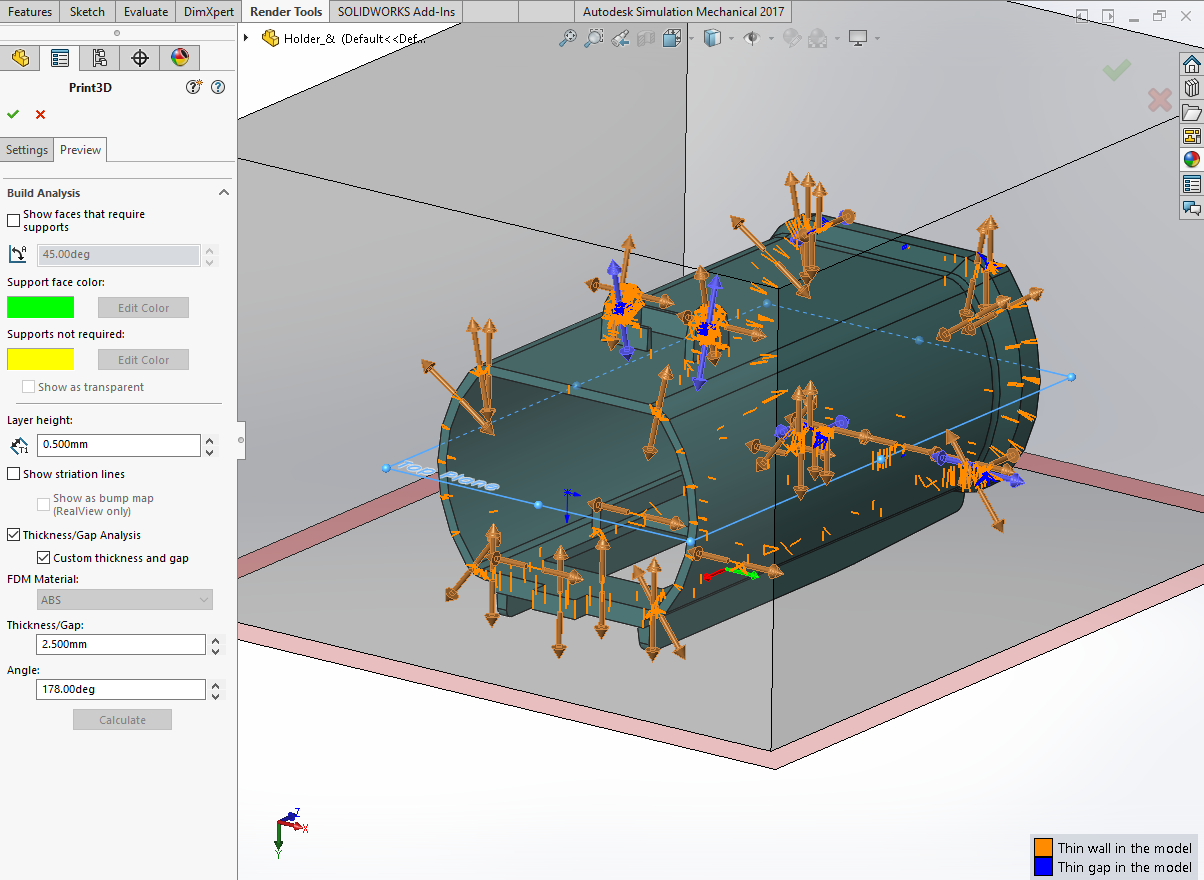
- Evaluating Models for 3D Printing
- PhotoView 360 Network Rendering Supports Frame-by-Frame Rendering
- Section View Updates
Display States now can manage different instances of decals and scenes. If you are using PhotoView 360 you can also configure light sources for all light types (including sunlight).

When generating section views you can now set components to be transparent. This helps to visualize the inside of models.

The new 3D Print tool works with the layer height and selected material to evaluate the model for printing (using Fused Deposition Modeling – FDM). As a result, you can quickly identify thickness and gap width issues before printing.
See it in Action!
Feature Image “Part Replacement” by MIKI Yoshihito


