Every summer holiday (that’s Christmas time in our part of the world,) I try to spend at least some of the time working on a project of some sort. There are always jobs to do around the house, and it’s nice to get a block of time to make progress, as weekends always seem to go by so fast. The project for Christmas 2014 was to tidy up the garden. We’ve never been happy with it since we bought the house, and I decided to simplify things a bit and turn one of the flower beds into a new lawn. The existing lawn was looking a bit sad, so I decided to rip that one up too.
First step was to hire a big hydraulic rotary hoe, and chew up the dirt a bit. What an awesome machine! So much grunt, and a real workout chasing it around the whole day. I raked out all the existing, dead grass, and got to work (with the help of my folks,) leveling out the soil with a straight-edge, and rolling it until it was almost bowling-green flat.
 The Preparatory Work
Now you may be wondering, what on earth this has to do with anything that Design and Motion is all about. I mean, this is more landscaping than engineering or other related geekery right? Well you see, I tend to get carried away with things. So the job that was initially going to be one new lawn, became two, and then I decided I wanted irrigation, and that got my imagination going… Irrigation could mean solenoid valves, and solenoid valves would mean electronic control, and electronic control could mean automation….. You get the idea.
What I have ended up with, is a completely automated lawn watering system, that has a live web feed from a weather site, that makes adjustments to it’s schedule based on seasonal variations and weather. I built the controller myself, for about $100, using completely open-source hardware and software. This is cool stuff, and exactly the sort of thing that gets me excited about how accessible automation technology is, to just about anybody now.
Having got the system up and running, I thought I’d detail the steps I went through to build the system, to share the process which I found really enjoyable.
Step 1 – Creating a digital representation of my garden
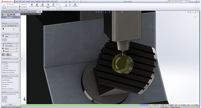
I could have just taken measurements down on a piece of paper and then drawn it up in AutoCAD…. but that would be so last millenium. I thought I’d try and be new-age, and use cloud tools and an iPad to get the job done. I started by finding my house on Google maps, and taking a screenshot of the satellite image of it. I then inserted that into AutoCAD (desktop to start with,) and got to work scaling, and tracing over it, to get the areas that I wanted. Here’s the result, with and without the underlay image:
 Capturing a House and Garden Plan in AutoCAD, using Google Maps Satellite Image
I spoke to these guys first, to see what information they’d need to be able to specify a system for me. They seemed very knowledgeable about irrigation components, but they handed me a piece of graph paper, with a 1cm = 1m scale, and told me to sketch my garden on it. Pah, what a joke. No way was I giving them some scrappy piece of paper. They did need dimensions though, so my scaled AutoCAD drawing was not going to be good enough on it’s own. I created a few dimensions in AutoCAD, and realised that the satellite imagery was too distorted to provide enough accuracy. I was going to have to take measurements with a tape measure, and annotate the drawing manually. Now walking around the garden with a laptop and a tape measure is not practical, and pencil and paper was breaking the rules, so I uploaded my .dwg from AutoCAD to AutoCAD 360, and set out into the garden with iPad in hand. It was surprisingly easy to take a measurement with the tape, and then just tap it onto the plan on the iPad. Within a very short space of time, I had all the data I needed and I headed back inside and sat down at my laptop. Like magic, all the work I had done outside was sitting there waiting for me in my web browser on the laptop! This is where the whole cloud tech thing really shines. It felt great to be using it for a real project, even if it was just a home job.
 Sketched Dimensions from the Garden were Automatically Transferred
Step 2 – Sourcing the components
I used my sketch dimension values to accurately scale and dimension the drawings to take to the irrigation people. They were very helpful, and had a system planned out and quoted for me very quickly. They gave me a list of items to buy, and loosely assembled the manifold for me so I had a reference for how it went together. There were a number of fittings, and getting the order correct was important. Obviously, I declined to purchase the electronic controller, and opted to switch the recommended AC solenoid valves for DC ones. In my head, I imagined that I would have an easier time controlling DC valves (as I was planning on using Arduino and Raspberry PI.) Boy, was I wrong. It turns out, that if I had done my research first, and gone with the AC valves, I could have just bought one of these open source controllers, which works out of the box with those valves. Too late, the DC valves were already in the ground, and where is the fun in buying an off-the-shelf solution anyway?
 The Manifold Components
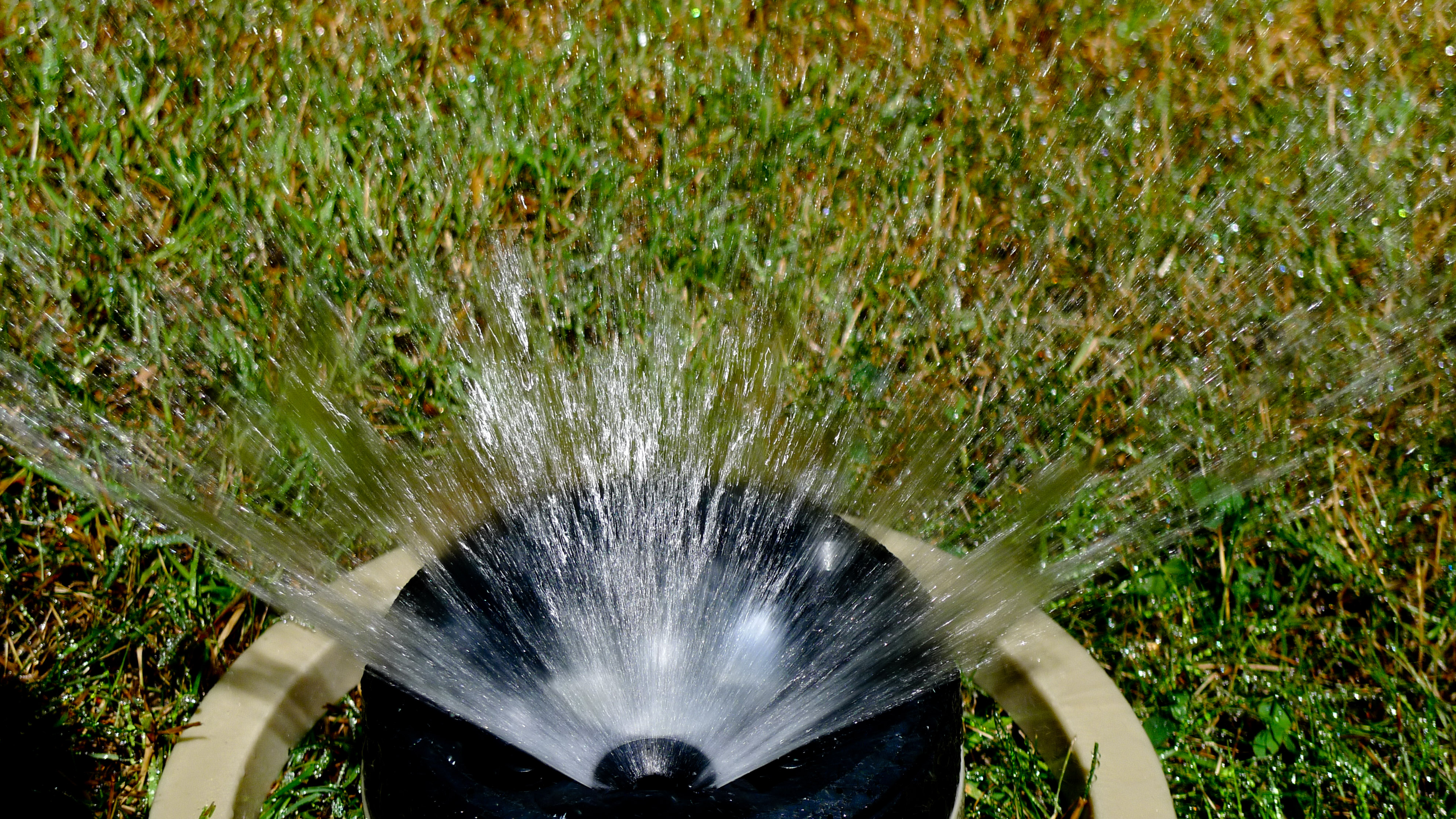
If anyone is interested, I can scan and post the parts list, but it’s basically just a number of Hunter Industries Pro-Spray bodies, with MP Rotator nozzles, and 20mm tube.
Step 3 – Building the Electronic Controller
This turned out to be more complicated than I first thought. Most likely because I had no idea what I was doing. All I new was that the solenoids required a 12-20V DC pulse of 40-120ms. The solenoids were of the latching variety, which meant they only needed that very short pulse to switch directions, with a reversal of polarity to reverse the directions. In between switching, they just sit passively, not consuming any power at all. This is great for an energy efficient system. Well that didn’t sound so bad, so I got a 12V battery from the garage, with a couple of leads on it, and did my best to estimate a 40-120ms pulse by flicking the battery leads across the solenoid coil wires. I heard a CLICK, and the one zone burst into life! I changed the leads around and repeated my trick to shut the circuit off….. nothing. I tried a few more times, but no joy. So now I was stuck with the sprinkler on, and no way to turn it off. Luckily, the rep at the irrigation shop had convinced me to install a manual shutoff valve, and I now understood the value in it.
After many hours googling, I finally discovered a different data sheet for my solenoids, that I had not seen before. In it, it specified a 4700uF capacitor as being a required component, but no information as to where, why, or how it should be implemented. After many more hours, and almost wearing out the google, I finally found a forum post by a chap who suggested that DC latching solenoids sometimes required more instantaneous current than the battery could provide, and putting a capacitor across the power supply could make up for the shortage. It sits there charging up in between valve switching operations, and unleashes it’s burst of current when the contacts on the relay close. I rigged up a complex array of automotive relays to provide a switchover circuit, and gave it a shot. Sure enough, I could now switch the sprinklers on and off, but I had a clumsy array of relays sitting on my desk, that I wasn’t happy with.
Enter the humble H-bridge. I had heard of this device before, and had even followed a tutorial to use one to control a DC motor, but never really found out what it was about. It’s a little arrangement of transistors and diodes, that can be used to flip the polarity of a circuit. This was exactly what I needed for my solenoid valves, so I found one that could deliver the appropriate amount of current, which was conveniently packaged as an Arduino shield. Perfect! A bit of mucking around with an arduino sketch, and I managed to completely replace the complex relay array with this neat little device.
Here’s the arduino sketch that drives it:
/* Zwapsprinkle - An open sprinkler controller using raspberry pi and Arduino */

//Set up the h-bridge
const int valve_a_signal = 9;
const int valve_b_signal = 8;
const int valve_a_enable  = 6;
const int valve_a_input_1 = 4;
const int valve_a_input_2 = 7;
const int valve_b_enable  = 5;
const int valve_b_input_3 = 3;
const int valve_b_input_4 = 2;
char inChar;

int valve_a_state = LOW;
int valve_b_state = LOW;
int valve_a_previous;
int valve_b_previous;
int valve_a_reading;
int valve_b_reading;
int out_state_a = LOW;
int out_state_b = LOW;

int debounceDelay = 150;
long lastDebounceTimeA = 0;  // the last time the state was toggled
long lastDebounceTimeB = 0;

void allInputsOff()
{
  digitalWrite( 4, LOW );
  digitalWrite( 7, LOW );
  digitalWrite( 6, LOW );
  digitalWrite( 3, LOW );
  digitalWrite( 2, LOW );
  digitalWrite( 5, LOW );
}

void valveAOn()
{
  Serial.println("Valve A on");
      analogWrite( valve_a_enable, 255);
      digitalWrite( valve_a_input_1, HIGH);
      digitalWrite( valve_a_input_2, LOW);
      delay(80);
      allInputsOff();
}

void valveAOff()
{
  Serial.println("Valve A off");
      analogWrite( valve_a_enable, 255);
      digitalWrite( valve_a_input_1, LOW);
      digitalWrite( valve_a_input_2, HIGH);
      delay(80);
      allInputsOff();
}

void valveBOn()
{
  Serial.println("Valve B on");
      analogWrite( valve_b_enable, 255);
      digitalWrite( valve_b_input_3, HIGH);
      digitalWrite( valve_b_input_4, LOW);
      delay(80);
      allInputsOff();
}

void valveBOff()
{
  Serial.println("Valve B off");
      analogWrite( valve_b_enable, 255);
      digitalWrite( valve_b_input_3, LOW);
      digitalWrite( valve_b_input_4, HIGH);
      delay(80);
      allInputsOff();
}

void setup(){
  Serial.begin(9600);
  allInputsOff();
  pinMode(valve_a_signal, INPUT_PULLUP);
  pinMode(valve_b_signal, INPUT_PULLUP);
  pinMode(valve_a_enable, OUTPUT);
  pinMode(valve_a_input_1, OUTPUT);
  pinMode(valve_a_input_2, OUTPUT);
  pinMode(valve_b_enable, OUTPUT);
  pinMode(valve_b_input_3, OUTPUT);
  pinMode(valve_b_input_4, OUTPUT);
}

void loop(){

   int valve_a_reading = digitalRead(valve_a_signal);
   int valve_b_reading = digitalRead(valve_b_signal);

//If the reading has changed
  if(valve_a_reading != valve_a_previous){
    // reset the debouncing timer
    lastDebounceTimeA = millis();
  }

  if((millis() - lastDebounceTimeA) > debounceDelay) {
    // whatever the reading is at, it's been there for longer
    // than the debounce delay, so take it as the actual current state:

    // if the state has changed:
    if(valve_a_reading != valve_a_state) {
        valve_a_state = valve_a_reading;

        if(valve_a_state == HIGH){
          valveAOff();
        }
        else{
          valveAOn();
        }

    }
  }
  // save the reading.  Next time through the loop,
  // it'll be the valve_a_previous value:
  valve_a_previous = valve_a_reading;

  if(valve_b_reading != valve_b_previous){
    lastDebounceTimeB = millis();
  }

  if((millis() - lastDebounceTimeB) > debounceDelay) {
      if(valve_b_reading != valve_b_state) {
       valve_b_state = valve_b_reading;

          if(valve_b_state == LOW){
            valveBOn();
          }
          else{
            valveBOff();
          }
      }
  }
  valve_b_previous = valve_b_reading;
}
(*edit: there was a bug in the debounce logic. Fixed now)
It simply watches the logic level of a couple of input pins, and provides the required 80ms pulses to the outputs when required.
Step 4 – The Scheduling System
I considered building the scheduling logic in an Arduino sketch, but decided that I wanted to really extend the scheduling with the ability to access a weather API and make decisions about when and how much to water, based on the conditions and forecast. Weather Underground is a fantastic resource for this, and allows up to 500 API calls per day, for free! For this capability, I decided that Raspberry Pi might be better suited to the task. After messing around writing a few python scripts, I decided to have another google, and see if someone had done the hard work for me. Initially I thought I might hack OpenSprinkler to work with my Arduino, but then I discovered sprinklers_pi, which was a lot simpler and would hopefully do what I needed. Sprinklers_pi is another open-source project that looked like it would provide all the functionality I wanted, and more. I set to work modifying the code to send the required signals to the Arduino. Using another open-source library called WiringPi, allowed me to control the GPIO pins on the Raspberry Pi, to send the logic signal to the Arduino input pins.
 The Raspberry Pi and Arduino Hooked Together
That was all I needed to get the valves flicking over, and I can now use the neat web interface provided by the sprinklers_pi web server running on the pi, to control the schedule.
 Clean Schedule Interface offered by sprinklers_pi
So far it’s working ok, although I did have an interesting problem last night, that the system can’t deal with. I did a bit of final testing, and configured the schedule before I went to bed. I woke up this morning, expecting to see the sprinklers on at 7am, but they weren’t. After some frantic rebooting of the system, and toggling the switches a few times, I thought I must have blown the solenoids. I went outside to open them manually and, lo and behold, someone had turned the main isolation valve off while we were asleep! This is a total mystery to me, and my only possible explanation, is that maybe an early morning dog walker saw the system on and thought he was doing me a favour by turning it off. Who knows, maybe a prankster. Anyway, I’ll probably end up putting a lockout on the valve.
If anyone is interested in more of the detail, let me know. Happy gardening!


