Following on from the first post about AutoCAD Mechanical last week. Here is my second installment:
Standards Based
The first area that sets it apart from AutoCAD is the standards management. Starting with one of the included standards you can build up your company’s standard. This includes layers and mapping the objects that should go on these layers. This means when you place things like dimensions the objects will automatically go to the appropriate layers.

Once you’ve completed your template and set it as the default, any non-AutoCAD Mechanical drawing opened in AutoCAD Mechanical will have the settings in this template applied to it. Need to update the current drawing to the standard? Just use the AMSETUPDWG function.
Adjusting the Drawing Scale can scale all annotation objects; dimensions, text, leaders, etc. Don’t worry about adjusting individual styles just change the scale and let AutoCAD Mechanical do the work.
AutoCAD Geometry Tools on Steroids
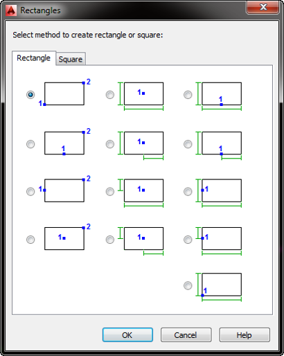
AutoCAD Mechanical takes typical AutoCAD tools and enhances them with semi-automated functionality or additional features. Take for example the rectangle command which in AutoCAD can be created one way, corner-to-corner. AutoCAD Mechanical expands on this giving you 13-different options for creating the rectangle.
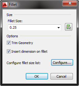
Fillets and Chamfers are dialog driven in AutoCAD Mechanical allowing you to quickly change settings on the fly, have access to regularly used sizes, and as a bonus double clicking on the arc or chamfered line allows you to quickly change the size.
AutoCAD Mechanical has methods to generate and work with construction (x-) lines and centerlines.

Content, Content, Content
AutoCAD Mechanical includes over 700,000 components based on international standards including ANSI, ISO, DIN, JIS, etc. This includes fasteners (nuts, bolts, washers), shaft components (clips, rings, bearings), and structural steel shapes. Need a Hex Head bolt? Don’t worry about drawing it, just pick the type, select the size and insert it.
The Content Library is 100% customizable. Alter the content by adding or removing sizes, add your company specific information like stock numbers and your descriptions. Also add your own components into the same library so all content uses the same interface. It’s a great way to have all your content in one location, using the same interface for locating and inserting.
Similar to Inventor you can use the Screw Connection wizard to quickly insert the bolt (or screw) with the nuts and washers. In addition use the built-in calculator to check and help size your bolt
Notice how it cleans up the geometry too. The Power View tool recognizes the selected component and generates the other orthographic views. Power Erase is a smarter erase command, recognizing the connection and removing it in entirety while cleaning up the geometry.
Other generators include the Spring, CAM, and Shaft Generator. Using the Shaft Generator you can lay out your shafts quickly and easily edit it afterwards via a double click. Once completed, use the Shaft Calculator on it to verify your design.
Every component inserted has structure (which we’ll talk about later) and is automatically included in the Bill of Material.
Hopefully you’ve seen a couple things you can implement immediately. The nice part of AutoCAD Mechanical is that it doesn’t require whole sale changes. You can pick features and implement them at your own pace. As a reseller, we once sold AutoCAD Mechanical to a firm and the only “Mechanical” specific feature they used were the Weld Symbols. Which they said saved them an estimated 25% of their detailing time.
In the next post we’ll look at the some of the annotation tools, the BOM features, and the unique ability to add structure to your 2D drawings.
THE OTHER POSTS IN THE SERIES:
Why should you use AutoCAD Mechanical? Part 1


