 InventorCAM 2010 is the easiest CAM application I had ever used. It is a full featured CAM toolset for milling applications up to 5 axis, and is capable of calculating just about any contour and model feature. It runs completely inside of Autodesk Inventor 2011, using the Inventor interface instead of a shell. It is so well integrated that CAD and CAM workflows can be completed in the same session.
I took a break from CAM and CNC for a while, but connecting with the company at Autodesk University 2009 compelled me to do some research during this past year, and joined the organization as an Alliance Partner. I reunited with the guys at Autodesk University 2010, and started missing my CNC time, so I decided to get the show on the road.
Let me start by saying that the folks at InventorCAM are quick to respond and are really helpful. They’ve checked in with me and asked if I need help a few times, but the darn thing is so easy to use, I can’t come up with anything that the application didn’t already prepare for me, at least not yet.
I had decided to start small, with a basic shaped component that had at least two operations, but was fairly simple with no contouring so I can check performance and setup easily. My wife had been eying me suspiciously from across the room. “What NEW software?” My messing around my workstation with a SolidCAM USB key in hand and evil grin and laugh, evoking the cold stare from she who calls Autodesk Design Solutions, “the Mistress”. hmmm… “but look, I’m making this for you…it’s a heart”. I received me a blank look and rolled eyes… at least Inventor still loves me.
So I went with the heart because it will get faced and profiled, and has a tight radius that I can use to check simple toolpaths.
Inventor Integration
There are two reasons I went with InventorCAM: Inventor integration and Setup.
As for integration, I’m not talking about “here is a toolbar to start it from Inventor, and it might even bring the part geometry over to the CAM program”, like some companies that claim to be integrated. You know who you are. I call BS.
No, InventorCAM 2010 is operated inside Inventor 2011, and you use Inventor tools that you are comfortable with to maneuver the component environment. The tool installs right into the Inventor Ribbon and communicates with Inventor directly to create native files as needed.

When a new InventorCAM project is started from within a part file, a new CAM Project folder is created within the Inventor Project file (or other customizable locations). The part file is seamlessly placed in an Inventor Assembly, which provides an easy method for InventorCAM to include models of stocks and fixtures if desired. Yes fixtures – I’m loving it.
Using Inventor while the tool is active is no problem as the context menu is still populated with Inventor tools and the Inventor Browsers are all accessible.
Setup
The Setup is so painless that it just didn’t seem right. 
The process acts kind of like a wizard, taking you from one basic workflow to another until the standard project parameters are established. Coordinate system, Stock, Targets, Tools, etc. Setting up a the coordinate systems is so easy, maybe one of the easiest setup systems I’ve ever seen. I started with the basic block configured by picking my part. It boxed out the limits of the shape on the top plane I selected. I then picked Pick Origin, and selected the corner of the box InventorCAM projected for me. We all have used apps that make this process a nightmare. This was so easy.
After an initial run with a basic box scenario, I went into the CAM assembly and created my own stock in place, which will allow me the easy ability to adjust anyhow I need, and like I said before, it’s all in Inventor. Then I simply told InventorCAM the new Solid was my stock and used it to establish the coordinate system as well. (Both Surfaces and Solids are no problem). I decided to test the integration by editing my stock dimensions in Inventor while InventorCAM was running. I simply right clicked the stock, and picked edit. The stock changes were picked up by InventorCAM since I had used the solid as my stock. Super Easy.
Creating tools was easy. In this respect I think most CAM applications are universal. I established 2 endmills in very little time, and was on my way to Geometries and Operations.

Operations
Operations are as easy to establish as the rest of the process. You could be dense as granite and still get through this process. I am betting my ten and twelve year olds can do this (we just may have to find out). While there are a lot of settings and configuration possibilities, the base common, day to day items are all set default.
Pick Profile Tool – Pick a part profile – select which side to cut… and you have material removal. There are so many other options like Roughing, Finishing, Compensations, Rest Materials, on and on that won’t fit into this article. (we can cover a lot more on this later). While defining one profile I decided some overlapped wall offset would be ideal, and thought, “where do I find that?”. I looked at the profile selection dialog, and offset was right where I needed it.


I’m using a clamped material base, so I need another pass on the underside. To do this we need to tell InventorCAM that a new position in the existing Machine Coordinate system is needed. Just tell InventorCAM where the new origin will be on the stock (or wherever) and show it how the part should be oriented. Numerous options are available, just choose the one that fits your needs. Once completed, a new position is established in the current Machine Coordinate system. Different systems can be established with as many nested positions as desired. Adding the final pass operation to the new position was just as simple. Once the operations were all set and calculated, I headed to Simulation.
Simulation
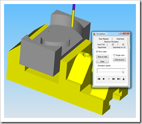
 There are numerous simulations available including 2D, 3D, machine, etc., but I think the SolidVerify for 3D is fantastic. I purposefully created 2 roughing profiles with 2 different radiuses to see how InventorCAM would react. Obviously the application should do this properly, but I needed to see how easy it would be to get it right without having to MAKE it. Not only did the application get it all down without me guiding each little step., but the Simulation reflected it beautifully.
It simulated each cut so I could check a few areas of concern. In the image you can see the roughing pass in the tighter radius. As each material removal operation is completed, the results are updated in the Simulation. The entire process can be simulated in one shot, or jump into the operations half way through if desired as well.
I forgot something along the way in my first run, and simulation balked and notified me that I was running the endmill shaft into the part. Not rocket science, but it’s nice to know it’s doing it’s job.
G-Code
The next step is to output the G-Code. This is where things could go haywire. I am using a software controller, and getting the two to talk the same language is a lot to ask. I generated the G-Code and it popped up in notepad.


I saved the file after a quick review, and loaded it in the controller for a dry run. Not a single glitch could be found. That in itself is truly impressive.
Comments
 I’ll cut the test part out this week to quickly verify that the code is solid (and that I didn’t foul something up). If anything goes wrong, I can pick up the phone and the InventorCAM guys will fix me up. I kind of wished I had developed a more difficult model to start with, because the entire operation went so fast. It would be fun to see how much time it took from start to finish without me peeking at all the options. I bet less than 20 minutes. I did go ahead and play with fixtures a little, it just looked too fun.
Now that the I have written up my preliminary impressions, we can get busy with some feature specifics and more detailed looks at the HSM module and 3D Contouring. Another thing I need to do is spend some time in simulation to see how fixture allowances are set and calculated.
Remember what I said in most of my CAM articles: “If you have to use it every day, the interface shouldn’t suck”. In terms of ease of use and intuitive nature, InventorCAM 2010 is top notch and definitely my favorite. It’s Intuitive nature made every step seem like I already knew how to use it. I would recommend this application to anyone.
I once voiced concerns over the toolpaths with the InventorCAM folks, in relation to some other company’s products that I had used and knew those features to be solid. They reminded me that the HSM package will make short work out of complex toolpaths. If that is true, it should make InventorCAM one of the best CAM tools in the industry. We’ll find out.
