
Inventor Sheet Metal Faces are great when first building the model, especially how you can lay out disconnected faces and connect them together during or after creation with bends. However, Faces are not the fastest member of the team… er feature set.

“Indy cars, bullet trains, supersonic aircraft… Sheet Metal Flanges leave them all in the dust.”
The Flash is iconic, and not just because he has his own TV series now. He was an important member of the Justice League, and not only because he was faster than Superman. He could run, thats for sure, but he also had many other super powers and was witty as a tack. Did you know during the Crisis of Infinite Earths, where worlds were literally colliding it was the Flash who sacrificed himself to save the world(s)?
Just like the Flash, Flanges have many hidden and unexpected features. Multiple edges can be selected during one operation. The flanges will auto-mitre. Individual flanges can be overridden using the onscreen glyphs. The bend location is adjustable.
Flanges are placed features, like fillets, chamfers, and holes. This means a sketch is not required to create the feature, however flanges cannot be the initial (base) feature of the model. The first step is to pick an edge. With the edge selected use the flip button to flip the direction of the flange, if it is going in the wrong direction. Adjust the height and bend radius as required.

The Bend Location can be of four options: Inside or Outside of Bend Extents, from Adjacent Face, or in some circumstances Bend tangent to side face.


The Height measured from one of three locations: Intersection of Two Outer Faces, intersection of Two Inner Faces, or Parallel to flange termination detail face.

Use the Aligned VS Orthogonal toggle to flip the height measurement between aligned with the flange face or orthogonal to the base face

Expanding the dialog reveals the Width Extents options, which include: Edge (the default), Width (either centered or offset from one edge), Offset, and From-To.

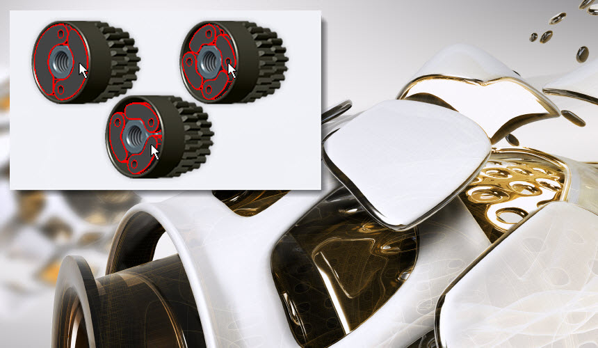
During the Flange creation you may select multiple edges, what’s powerful about this is that Inventor will auto-mitre the face intersections AND apply the proper corner conditions (based on the Sheet Metal styles)

Those little icons (glyphs) that appear on the flanges within the modeling window allow for the overriding of settings per flange

Let’s take a tour and see the feature in action…
As you can see Flanges are quick to build up the Sheet Model models, but yet still contain enough options to build the model correctly and as desired
Feature image photographed by Ryan McGuire
