
A key member of the Justice League was the Black Canary. At first glance she might seem a weak addition to the team, especially compared to other, more powerful, members like Wonder Woman and Superman. However, looking a bit closer you will see a heroine who is a world-class martial artist, with quick reflexes (enable to catch (or destroy) arrows in flight), and she is an expert motorcyclist. She also has a super powerful “Canary Cry“, which is a high-powered sonic scream that can shatter objects and incapacitate enemies.

DC Classics Black Canary at the Mattel booth at San Diego Comic-Con International by Loren Javier
What does this have to do with Flat Patterns? At first glance, the Inventor Flat Pattern tool is a simple one-click create flat pattern model. However, like the Black Canary, there is much more going on.
Creating Flat Patterns
Generate the Flat Pattern at any point during the model creation. Changes to the Folded model automatically apply to the Flat Pattern, meaning there is no advantage to waiting til the end. You can create the Flat Pattern whenever you need to see / check it. The Flat Pattern appears to open in another Window, which it is, however it is part of the same file. Use the browser to toggle back-and-forth between the Flat and Folded models.

Inventor 2016 introduced the option for multi-solid sheet metal files, however a sheet metal file can contain only one flat pattern. This means you need to Make Components to derive each solid as its own file to create the individual flat patterns.
Before creating the flat pattern you can define the “up direction” of the part, which is referred to as the A-Side.If you do not specify the A-Side then the base feature orientation is used.
Working with the Flat Pattern
The browser provides access to a couple hidden gems. Right-clicking on the flat pattern provides tools for seeing the flat pattern extents, exporting the flat pattern, and modifying the flat pattern definition. The Flat Pattern Extents are read-only but are available in the drawing environment for insertion as text. Use Save Copy As to export the flat pattern WITHOUT first creating a drawing… that’s right, direct exporting… no drawing.

Editing the Flat Pattern Definition provides options for adjusting the flat pattern’s orientation, how punches are displayed, and how Bend Angles are measured.
- Adjust the flat pattern orientation by selecting any straight edge, two points, or tangency line and specifying the line to be horizontal, vertical, or a user specified angle from horizontal / vertical. Each flat pattern orientation can be saved to be restored at a later time. Flip the Base Face to reorient the flat pattern, flipping the back face to become the front face.
- Punches can be displayed in one of five options: default (based on the style), Formed (3D representation), 2D Sketch, 2D Sketch with Center Mark, and Center Mark
- The Bend Angles can be measured using the outside face (A) or the inside face (B).

Editing the Flat Pattern
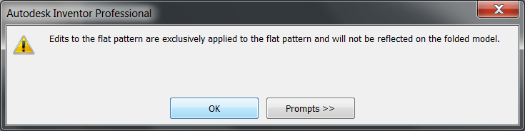
Within the Flat Pattern changes can be made, features added, that only impact the flat pattern. Yes, you read that right, features you add to the flat pattern do not transfer back to the folded model and this is by design. Why? Its so you can make flat pattern adjustments for manufacturing allowances. Back in my reseller days I spend a significant amount of time with a company that did sheet metal for a living. They got to the point where they had different sets of bend allowances & corrections for day shift vs night shift, and in some cases per operator! They had special punches and cutouts that they added to the flat pattern so that the sheets bent and formed correctly. It would be nearly impossible and definitely not worth the effort to model these in the folded model. In these scenarios the features are added within the flat pattern.
Nothing special about adding features. Create a sketch and create a feature, or add placed features like fillets, holes, and chamfers. The feature set is not as extensive as the regular modeling environment, but the intention here is to provide tools to remove material from the flat pattern.

There are however two Flat Pattern specific tools: Cosmetic Centerline and Bend Order Annotation
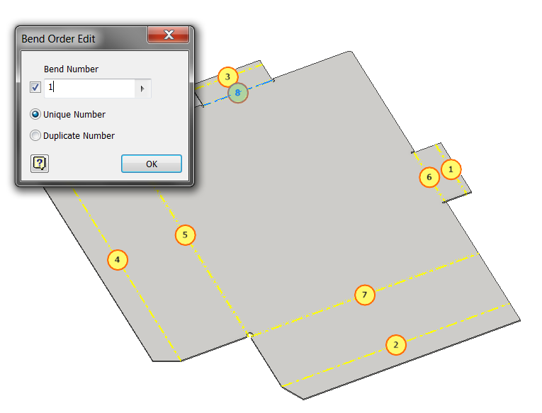
Within the drawing environment the bends can be automatically labelled providing the order the bends should be performed in. The order defaults to the order they were created, but the order can be a bit jumbled especially when the flange feature is used to create multiple bends in one operation.
With Bend Order Annotation you set the order of operation. The colouring of the glyphs provide instant feedback on what are original and what have been overridden. Bends are re-sequenced by:
- Directly by specifying the starting and ending glyph and allowing Inventor to renumber everything in between
- Sequentially by selecting a bend which becomes #1, and the rest are renumbered, then the next selection becomes #2, and the remaining are renumbered, and so on and so on.
- Individually by selecting and changing specific bends
TIP: The right-click menu provides a “remove overrides” option to set the order back to the default.
Cosmetic centerlines provide a mechanism to add bend / fold lines to the flat pattern that are not a feature. The help lists the following examples: a die-formed lofted flange model that requires manufacture using a press brake, cross-break (stiffening) creases or flattened features which contain no bend zone extents (spline face). Cosmetic Centerlines are sketched based features, meaning you need to create a sketch first containing lines to represent the centerlines.

See it in Action!
Featured Image “Wonder-Con 2012: Black Canary” by gamefan23 (Jason E.)

