
You’ve started a new model, worked hard, and it’s looking good…. but then it happens, you realize it should have been made in the sheet metal environment! Or a different scenario, you’ve imported a model but its come in as a solid blob and you need to flatten it out.
This is my continuation of a series taking a deep dive into Inventor’s Sheet Metal environment. There isn’t really an order that they have to be read, but you can start with the first one here Holy Sheet Metal Batman!
Autodesk Inventor allows for converting models to sheet metal. Which means, regardless where the model geometry originates, you can convert it to sheet metal, add sheet metal features, and generate the flat pattern.
Let’s start with the rules of sheet metal
- Rule #1 You must have a consistent thickness
- Rule #2 Your sheet metal thickness parameter MUST match the thickness of the model
- Rule #3 You cannot have one continuous face, there must be some type of gap
- Rule #4 Although Inventor now supports sharp corners there still needs to be a round (fillet) on the outside edge
Say we start with something like this. I know what you are thinking…. “that’s simple, we don’t model anything like that“… but we’re going to use this shelled box to showcase the features required for the conversion.

Converting Models to Sheet Metal with Autodesk Inventor
First step, activate the Sheet Metal Environment. This actually does more than just activate a set of tools, it automatically creates a set of parameters, the ones required for the sheet metal “magic” to happen

I know as a shelled box we’ve got a model with a consistent thickness, I just need to tell Inventor what to use. Within the Sheet Metal Defaults dialog, I can either edit the rule to define the thickness or as in this example I override the rule thickness and specify the value to use

Now lets add a Corner Seam using the Rip option. The Rip option is purposely built to work with part models converted to sheet metal. It creates the required break in the faces so that model can be flattened. One small problem, and I quote the help here “You can rip a corner seam to open an edge between faces. The resulting open corner typically leaves material that must be removed.”
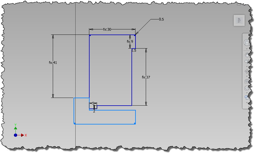
If we skip ahead and look at the final result (Corner Rip + 2 Bends) I can see a small remnant that must be removed. It’s not really a problem, just a bit of extra work.
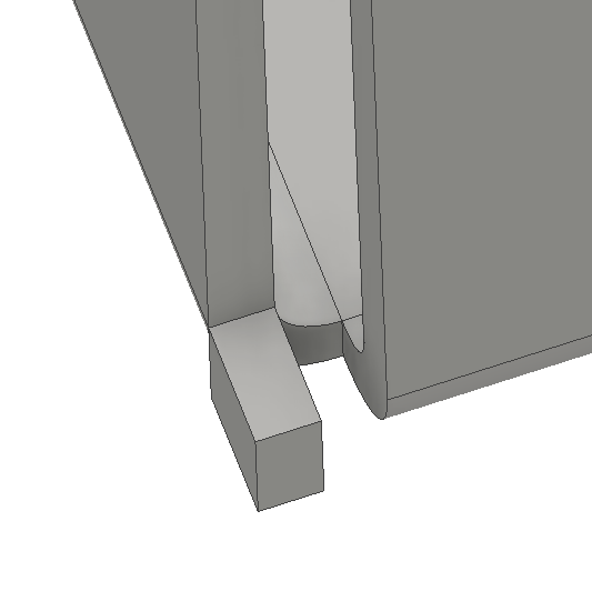
Is there a way to do this without needing a sketch and extrusion after? How about when I create the Corner Rip I specify the overlap option instead, even though my final result is to not overlap in the corner

Next I add Bends in the corners. I could do this with fillets, but the Bend feature takes care of rounding both the inside and outside edges, as well as setting the radius to the BendRadius parameter. In my example, I need to apply two Bends.

The resultant corner is not ideal but is exactly what I asked Inventor to create.

To produce the desired condition I apply another Corner Seam, but this time using the Seam option

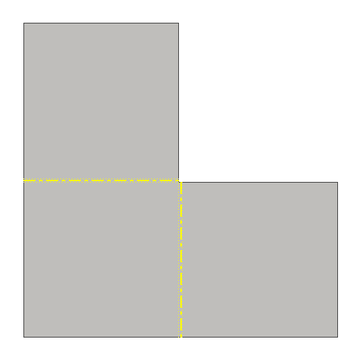
I now can produce the flat pattern
Data Conversion
Here is a model originally modeled with Solidworks that I opened (and converted) into Inventor. As it was modeled using the Solidworks Sheet Metal tools the conversion process is very straight forward. It’s not just with Solidworks files though, you’ll probably find any sheet metal modeled solid transfers into the Inventor sheet metal environment seamlessly.

After initiating the Sheet Metal environment, Inventor prompts to select the Base Face. Upon selecting the base face, it extracts the thickness of the selection as the thickness parameter

And with this model that is all that is required. I can now create the flat pattern

I can guarantee that it will not always be this simple, although Inventor 2016 seems much better at translating data.
I have seen many Solidworks models that for whatever reason just don’t flatten, even though it follows all of the Sheet Metal rules. The trick I have found is to copy the imported solid into the construction environment, delete the original model, and then copy the construction solid back out. Whatever Inventor does during this process I do not completely know, but who am I to question something that works?
Further Resources
Having further issues attempting to get a flat pattern from your Sheet Metal model (converted or native to Inventor)? Paul Munford has posted a great article with Seven tips to guarantee that Your Autodesk Inventor Sheet Metal models will flat pattern without errors. Check it out here… Autodesk Inventor Sheet Metal, Flat pattern success – Every time!
Feature image sheet metal and nature by Robert Bejil
