Last year Autodesk purchased NEI Nastran. This was a good purchase because Nastran is a respected Name in analysis; it’s powerful and used in numerous industries. Furthermore, Nei developed a CAD embedded UI in Solidworks for the Nei Nastran solver, called Nastran In-Cad
Autodesk adapted In-CAD for Inventor, which now gives their Inventor users the ability to perform a large array of studies, including transient and non-linear analyses, right from the comfort of Inventor. Inventor acts as the pre and post processor for the Nastran solver.
We decided to take a look at In-CAD, and see how the UI and processor’s behaved. This article will focus on the basic features, and discussions on using the software, helpful tips, and results will be forthcoming.
User Interface
The UI is divided between a Nastran In-CAD tab, and the Browser.
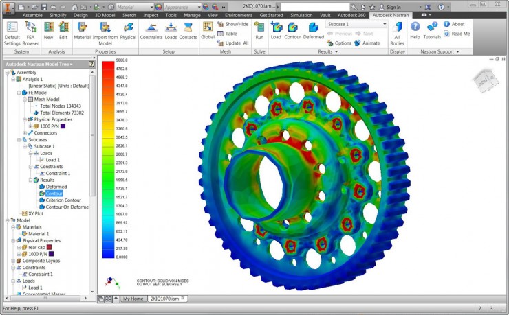
Image courtesy of Autodesk
Nastran In-CAD Ribbon tab
This displays a new set of Ribbon panels dedicated to the analysis model. These panels include settings, meshing tools, boundary condition applications, results plotting, etc.
Browser
The Browser is populated not only the Model and Assembly component sets, but three additional Nastran panels.
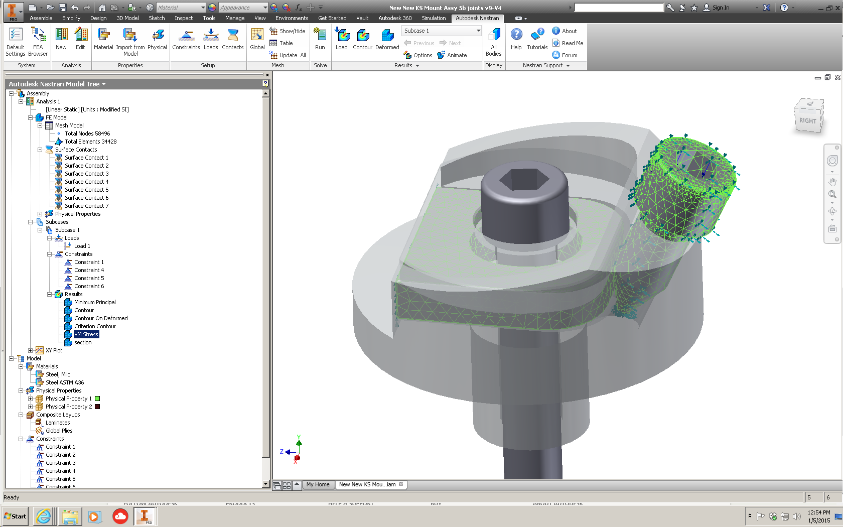
Nasrtan Model Tree
Nastran Model Tree is divided into the assembly and model groups. The Model group accounts for all boundary conditions and templates defined in the model. The analysis group assign these to individual analyses and subsets as the user dictates to accomplish different studies.
Nastran File
This gives users a look into the Nastran file data rather than trying to interpret everything through the CAD interface.
Nastran Output (Log)
The output window shows the progress of the Nastran run, including real-time convergence data. This browser window is displayed by default during the run process. Once solved, this output log can be reviewed as needed and the contents thereof are saved along-side the other Nastran model and results files.
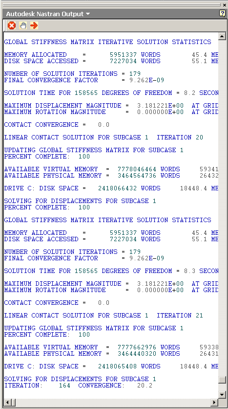
From this window the analysis can be stopped, paused, and resumed.
Autodesk Nastran solver
The Autodesk Nastran (formerly Nei Nastran) solver’s accuracy is routinely tested against the NAFEMS standards at every release. Mitch Muncy, Product Manager for Autodesk’s Nastran product came along with the Nei purchase, and has stated that the company had spent countless hours verifying every detail of the solver, to ensure that it met the advanced requirements of its customers in industries such as aviation and automotive.
Linear, static stress, thermal, and modal analyses
Prestress static – response of complex loading
Static fatigue – repeated loading cycles
Heat transfer – conduction and convection heat in examination of temperature distribution
Linear buckling – compression induced loss of stiffness
Linear statics – stress, strain, and deformation from applied static loads and constraints
Normal modes – component natural frequencies
Advanced analyses
Pre-stress normal modes- capture true stiffness when complex loading is present
Frequency response – structural harmonic response based on frequency-dependent loads
Random vibration fatigue – long-term structural robustness where operation must be characterized by power spectral density (PSD) inputs
Transient response – response through a period of time under the influence of constant or time-dependent loads
Random response – behavior due to imposed of random dynamic loads, such as road vibration, wave cycles, engine vibration, and wind loads
Nonlinear static and transient response – time-varying events including dynamic loading that result in resonant vibration or stress amplification
Superior surface contact, impact analysis, and automated drop tests – includes nonlinearities of large deformations, sliding contact, and nonlinear materials
Advanced material models – complex nonlinear phenomena, including plasticity, hyper-elasticity, and shape-memory effects
Composites – straightforward complex ply data, and progressive ply failure, including Puck and LaRC02 algorithms
Element Types and Modeling
1D, 2D, and 3D element types open a whole new world of modeling capabilities. Beam elements for example offer high performance connectivity in the model at a tiny fraction of the memory and processing power required to study a 3D meshed solid in the same situations. This offers flexibility that linear static analyses never offered.
Automatic bolt connector modeling with preload – simplified setup
Associative intelligent meshing
Thoughts
We wanted to give a feel for this software to both Inventor users wanting more analysis power, as well as Nastran users that were considering a CAD based environment. The In-CAD interface brings Nastran to Inventor users, and puts a lot more power at their disposal. In our next edition I’ll take Autodesk Nastran In-CAD for a spin with a simple setup and analysis run, in order to try and give all parties a feel for what they might expect.


