Love it or hate it, Microsoft Excel is an indispensable tool for most design engineers. It provides a very quick and easy way of recording, visualizing and performing calculations on data. Often, the calculations performed in excel provide results that are used to determine the dimensional and geometric data that is then created in the CAD application. Some more advanced users will use the spreadsheet to actually drive parameters in their 3D model. While this can be a very useful workflow, there is still an element of manual re-calculation and updates that can be time-consuming.
What if we could have our CAD model, feeding live data to Excel, which is simultaneously performing calculations on said data, and feeding the results back to the CAD application? This would allow the user to remain in the 3D modelling environment whilst still leveraging the calculation powers of Excel. The answer is (as is often the case when you ask me) iLogic in Autodesk Inventor!
Hypothetical Design Scenario
You are required to specify an electric motor / gearbox combination that will be used to tip a mixer bowl that is used for mixing huge batches of pancake batter. The motor/gearbox output shaft will be connected to the shaft that forms the pivot for the bowl. You intuitively have an idea of where you might position the pivot point, but knowing that the center-of-mass of the liquid will change as it pours out, you need to be fairly accurate to optimise the motor/gearbox size for the job.
Now there are a few factors at play here. As the bowl tips, the volume of the liquid will start to decrease, but not linearly, partly due to the fact that the bowl is round. In other words, this is a 3D problem. While the center-of-mass will remain on the center plane of the bowl, it will move in both of the other two planes during the tipping cycle. We could calculate the volume at a series of time steps, use that data to calculate the mass and center-of-mass position, and then use that to determine the moment at the pivot, but it seems like a lot of work when Inventor already understands volume and mass as properties of a solid.
Attacking the Problem
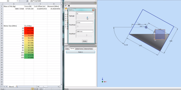
To start off, I created a surface model of the bowl that I could tip using an angle parameter whose value could be driven using a slider in an iLogic form. It’s range of motion is 0 to 90 degrees. I constructed the geometry using the origin of the part as the pivot point of the bowl. I then created some parameters to move the bowl geometry around the pivot point which allows me to control the offset. By defining a workplane at the level of the “spout” that remains horizontal, I could represent the surface level of the liquid. Using the “Sculpt” tool in Inventor, I then created a solid body to represent the volume of the fluid. As the bowl is tipped, the fluid volume reduces accordingly.

Now that I have a mechanical representation of the problem, I harnessed the power of iLogic to share the numerical information with Excel as follows. First I created an iLogic form to expose the parameters for the tip angle and pivot offsets and created sliders to adjust the values. Next I created parameters to store the volume and mass of the liquid, and also the horizontal offset distance between the pivot point and the current center-of-mass of the liquid. The last Inventor step was to create the following rule in iLogic:
'Get the current offset between center of mass and pivot point in horizontal plane

'and assign that value to the relevant parameter.

CoGX = iProperties.CenterOfGravity.x
'Pass the offset value to excel (divide by 1000 to give meters)

GoExcel.CellValue("3rd Party:Embedding 1", "Sheet1", "C2") = CoGX / 1000
'Get the current volume of the metal and assign it to the AluVol parameter.

AluVol = iProperties.Volume/1000 '(in cm^3)
 'Create variable to hold the density of the current material

materialDensity = ThisDoc.Document.ComponentDefinition.Material.Density '(g/cm^3)
'Calculate the mass of the metal in kg

AluMass = (AluVol * materialDensity)/1000 ' (in kg)
'Pass the mass to Excel

GoExcel.CellValue("3rd Party:Embedding 1", "Sheet1", "A2") = AluMass
'The following lines have been commented out. They were included as a crude form

'of data-logging so that the movement of the center-of-mass could be graphed in Excel.

'GoExcel.CellValue("3rd Party:Embedding 1", "Sheet1", "E" & Index) = TipAngle

'GoExcel.CellValue("3rd Party:Embedding 1", "Sheet1", "F" & Index) = AluMass

'Index = Index + 1
'Update the document immediately to see changes as a smooth animation.

InventorVb.DocumentUpdate()

Once the data was in Excel and the spreadsheet had been embedded in the part file, I created a few formulas to calculate the current moment (torque) due to the mass of the liquid at the pivot point (ignoring the mass of the bowl itself). I also put a list of motors down the side which were specified based on maximum torque that they could provide. Using conditional formatting, I could then change the colour of the cells that represent each motor size based on the ratio between current torque required and maximum torque available from the motor. This gave me a nice visual representation of the suitability of each motor size. Red meaning the motor is overloaded (over 100% of maximum torque) and green being underutilised (not an efficient choice). By adjusting the sliders in the inventor form and running the model through the tip cycle, you can get an idea of which motor provides the best choice. The Excel spreadsheet can remain open while you adjust the model parameters and iLogic ensures that the calculations remain live.
In summary, this workflow is not about using some magical powers of Inventor to provide calculation that was otherwise impossible. It’s actually about thinking about the calculation/modelling flow differently. As I said earlier, most engineers/designers already use Excel all the time, so why not integrate it in a way that is seamless between the engineering and design phases. Anyway, enough text, watch the following video to see it in action.
Edit: Here’s the file for those of you who’d like to have a play with it.
[subscribe2]

