
Sheet Views
Now that we know how to work with the Sheet Set Manager and add Sheets we’re going to dive in and explore how adding Sheet Views is accomplished. This is a continuation of our series taking a deep dive into AutoCAD Sheet Sets. If you’d like to start at the beginning, take a look at the table of contents.
The high-level overview of adding views…
- Add the file locations to the drawings containing the views
- Drag-and-drop model space views onto your Sheets
- AutoCAD attaches the drawing as an XREF, generates a Viewport, and sets the scale
Location, Location, Location
First, you need a drawing open and it doesn’t matter what it is, or if you intend to keep it. Now, you can add the file locations to the drawings that contain the views. Using the Model Views tab, double-click on Add New Location. Browse to and select the folder containing the drawings.

Expand the drawing for the list of available model space views.

To remove a location, right-click on it. From the menu select Remove Location.
Drag-and-Drop to Add Views
To add the view to your drawing, drag-and-drop from the Sheet Set Manager onto the Paper Space Layout. AutoCAD generates a preview to aid in the positioning and scaling. To adjust the scale, right-click, and pick the desired scale. The preview updates so that you can position the view properly. Left click to place the Sheet Views.

As the view is placed a view callout is automatically placed. [We’ll dive into building these labels in a future post.]
Let the Magic Happen
As the view is placed, its drawing is attached as an external reference (xref) and inserted into model space. A viewport is created at the extents of the view and scaled according to the scale you’ve selected.

Once placed, the viewport created is a standard AutoCAD viewport. This means you can use standard features like grips, Properties, and the scale list to make adjustments.
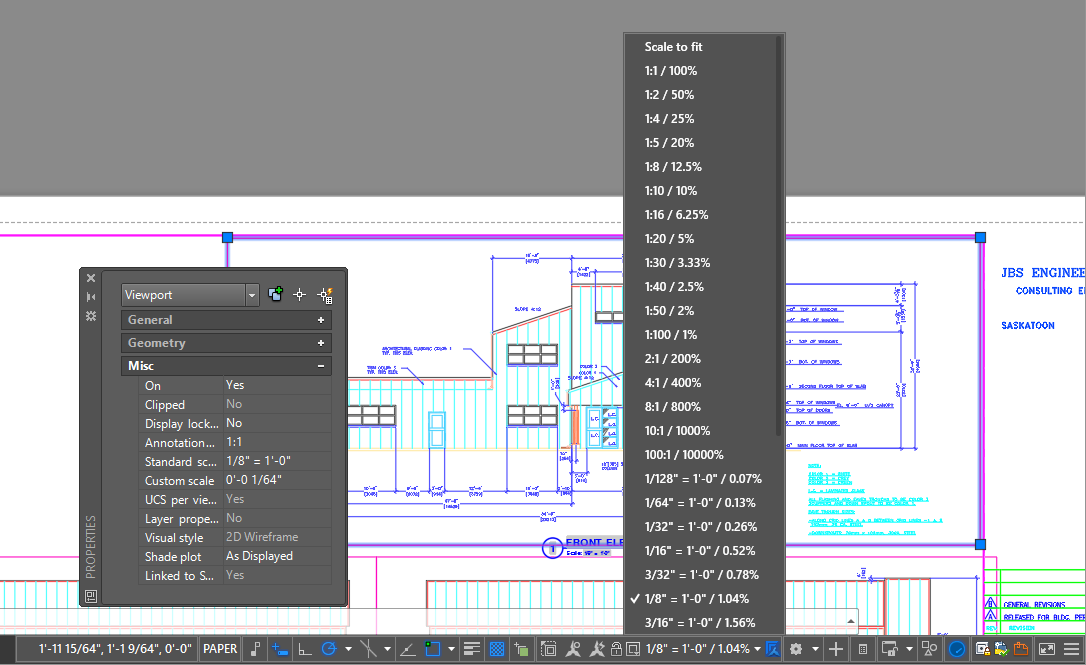
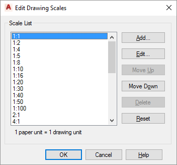
Modifying the Scale List
Use SCALELISTEDIT to make changes to the available scales. These scales are available both during View placement from the Sheet Set Manager as well as when modifying an existing Viewport. This is something to consider saving within your template.
Building Model Views
Using the VIEW command, create Model Views of the portions of the drawing you want to add as views to your Sheets.
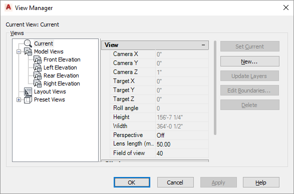
Start by clicking New and use the New View / Shot Properties dialog to define the new view. Specify the name and optionally a category. Categories are advantageous to group like views. The View type should be set Still.

Many of the options are only valuable when capturing 3D Views. Since you are creating views for a Sheet Set, the only important settings are the Boundary and saving the layer snapshot. Always leave the UCS as World, Live Section to <None>, the Visual style to Current or 2D Wireframe, and the Background as Default.
The Boundary can be either the Current display, if you like how you have zoomed into the drawing, or Define Window to pick the boundary of the view.
Enable Save layer snapshot with view to capture the current state of the layers. This includes the ON / OFF state, Freeze / THAW, LOCK, and properties like the layer color. When restoring the view, AutoCAD also restores the saved layer state.
When you click OK the view is created and is listed within the Model Views list.
Lights, Camera, Action!
Feature Image “view” by Gabriel White


