Layer Translator
You’ve received a batch of drawings from an outside source… customer, vendor, sub-contractor… and the layers do not match your own company standards for layers. The properties are wrong, the names are different, and you’re looking at a lot of work to get the drawings to standard. Don’t fear, our AutoCAD Layers Deep Dive series delivers the Layer Translator!
 The Layer Translator is used to map a set of layers to the standard set of your choosing. If the layer in the drawing is called A-Wall-Partition and your standard calls for WALLS you would map the layer so that WALLS is added to the drawing and all objects currently on A-Wall-Partition are moved to WALLS and take on the properties of WALLS. A-Wall-Partition would be removed from the drawing.
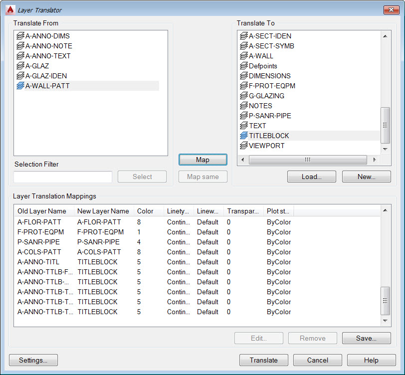
From the CAD Standards Tools select Layer Translator. Use the Load button to add the desired layers, the ones you want to map to. You can use existing drawings (DWG), templates (DWT), and standards (DWS).
 The Map Same button is used to match layers that have the exact same name, but more than that it insures that these layers have the same properties as the destination layers.
After using Map same you go through the list mapping the layers to their target. In this example I take all A-ANNO-TTLB layers and map them to the TITLEBLOCK layer. Not all layers need to be mapped as you can leave layers as they are.
 Once you are satisfied with the mappings you can save this as a drawing. This mappings drawing can then be used to load in the mappings into other drawings you have received from the outside source
Select Translate to make the magic happen!

Reconciling Layers
Once the layers have been translated, or really with any drawing, how do you manage the layers so that you are aware of layers that are added? Especially in situations where you are not even aware that layers have been added, like when you insert a block. For this you can use the built in Layer Reconciliation process. The AutoCAD Help explains it the best…
“Unreconciled layers are new layers that have been added to the drawing and have not yet been acknowledged by the user and manually marked as reconciled.“
The base in which AutoCAD uses to compare is set the first time the drawing is saved. At this initial save the existing layers are reconciled and all new layers added, either manually or by some other process, are considered unreconciled. Now sirens, buzzers, and warnings are not going to start just because an unreconciled layer has been found, but it gives you the option to review these layers at any time and decide what to do with them
The Layer Settings are important with this feature. If you want to use the Reconcile option you need to enable New Layer Notification and select whether just to evaluate xrefs or all new layers. You also need to configure when you want AutoCAD to notify you of new (unreconciled) layers. The options are on Open, xref attach / detach, Restore layer states, on save, and on block insert.
 Within the Layer dialog a layer filter is automatically created to isolate just unreconciled layers. To reconcile the layers (accepting them to the drawing) right-click on them and select reconcile)
 When new layers are added you will see a message similar to this….
 In Review
Hopefully I’ve shown you a couple tools to not only take a drawing and make it to your standard, at least layer wise, but shown another option for keeping you within your defined standards. If you liked this article let us know using the comments below and keep an eye out for the next in our series of diving deep on AutoCAD Layers.


