Ok, it’s been awhile. Everyone knows I am studying for the test, but I feel so bad for all the people who have been emailing me about the series. I will run through the ‘Homework’, and then complete the configuration session soon hereafter.
Homework Review
We left off with your homework, which was to transfer the Toe plane out, and complete the transitions. I’ll recap it as I run through.
Create the Toe Plane, Offset from the Right Plane a distance of ‘(bHeight-bThick)*bSlope’. Insert the Anchors.
Don’t forget the model parameters for the offset distances.
Create the appropriate BASE, LEFT, and RIGHT PROFILES, dimension and constrain them properly. The Width and Height of the LEFT PROFILE is ‘bThick’ (You decide how to get the RIGHT PROFILE sized properly, dimensions or constraints). The Width of the BASE PROFILE is the width of the Mid Plane BASE PROFILE.
Just add 3 Rectangular Profiles and make it look like Tetris.
Then dimension them and constrain them once their in the view. I do them one region at a time.
Add the Dimension to the Base width and Height, and then immediately edit the dimensions. I do because I can’t remember which is which. The base width was to be equal to the mid plane BASE PROFILE (I had LenA9).
Then do the same for the LEFT WALL (‘bThick’ on Height and Width). Add Equal constraints from the top of the LEFT WALL in relation to the RIGHT WALL, and then the side of the LEFT related to the side of the RIGHT.
Add an Equal Distance constraint from the top 2 points of the BASE PROFILE to the anchor point, and then a dimension that ties the top of the BASE to the anchor line, with a dimension of the Mid Plane height ( I had LenA8 in mine).
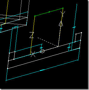
Then Constrain the bottom of the LEFT WALL Coincident to the top of the BASE. Add a constraint to the left edge of the LEFT WALL Coincident to the left edge of the BASE. Do the same for the RIGHT WALL, the right and bottom edges coincident to the Right and Top edges of the BASE PROFILE.
It should look like the image above.
Add the 3 Transitions. You’ll get no credit if you can’t create the Transitions because you could not select the Mid Plane Profiles. (That’s 2 hints in 1, by the way)
What that meant was you will need to change the view of the model such that you can select and see the MID PLANE PROFILES. The transition is probably in the way, so turn off the visibility. Expand the Modifiers menu, and right click each to the visible transitions, and deselect Visibility. Each of the MID PLANE PROFILES should be available.
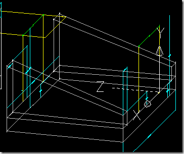
Through the Modifiers Right Click menu, create the Transitions, from the BASE PROFILE on the TOE PLANE to the MID PLANE, and again for the LEFT, and then the RIGHT PROFILES.
You should have something similar to this image below.
Save your work!
Verifying the Slope Equations
Turn on all the Transitions.
In the image below I have turned off all dimensions by going through the Dimension collection in each of the Planes, and deselected the visibility of each dimension, so that you can see this more clearly.
You should be able to see where I have marked the top of each of the profiles respectively. I have rotated the view such that each of the tops line up visibly. Note that it is a straight line along each top edge. This is our litmus test for the geometry and equations.
That is the structural part of the session.
Placement Point
The Placement Point defines how the Pipe will connect to the Structure. The thing is that it doesn’t connect like you would think. I would think that the Placement Point would be the invert of the pipe. However that is variable in the Structure Properties. Since the application has to calculate the location of everything in relation to the top of the structure, the remainder of the math is related to the TOP PLANE. So, Autodesk decided to relate this placement along the TOP PLANE, and subtract the respective distances as needed to complete it’s calcs. If you spend some time reviewing the Structure Properties, it may begin to make sense.
In the image above I have set the Placement Point at the RIGHT PLANE Anchor Point.
Autolayout Data Menu->right click the Layout Data item->Set Placement Point
Use the Node Osnap to select the Middle anchor for the RIGHT PLANE.
The Cyan circle should move to that location.
Next Session
In the next session I will cover Suring up the Model Parameters, validating the Structure, modifying the Size Parameters (which is how we get the ranges and lists started), making the Bitmap preview, and fixing the D*&N XML file so that it actually works.
Sorry I had to cut it off, but this way you get to review the current session while I complete the next.


