 I started a new Certification study project, and came up with the desire to grade a corridor over an existing creek. Yeah, DEP would be a problem, but let’s pretend I got the permit……. anyway.
I wanted a headwall and culvert combination to convey the creek safely past the improvements. The OEM Headwall is flat, and cannot handle the amount of grading going on around it. I, as usual, wanted something different than what was commonly available. I want a concrete wingwall, sloped according to the finished grade. I had a BRIGHT IDEA! I’ll use PART BUILDER!!
Fortunately for everyone, I have already spent a week of evenings going through this process, reading what others had to say online, looking for answers, and helping some individuals along the way. The only thing not happening is MY STUDIES. So I decided to make something good out of all the time I spent, and walk everyone through a basic, and not so basic, Part Builder creation.
New Part Creation
We need to start out with a new Chapter under the Structure Catalog. (You don’t have to add a new Chapter, but once you get going and want to test different things, it makes cleanup much easier.) The name can be anything, but it should be representative or what it contains. Right Click on the US Imperial Structure Catalog, and select ‘Add Chapter’. The dialog will appear allowing us to enter the new Chapter name.

I used Inlet-Outlet-Custom for my Chapter.
Now we can right click on the new Chapter, and select ‘Add New Parametric Part’. This will allow our new part to be adjustable.

The following dialog will appear asking for the Name of the Part, as well as a description that will be used to represent the part in various situations. Be careful with this because the description, not the name, will be the only thing you see in some cases in Civil 3D. The description will default to the name that you enter. I used Wingwall Sloped.
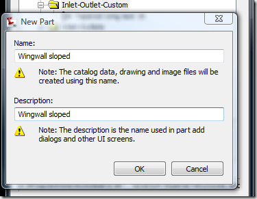
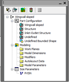
Hit OK, and the application will create an empty drawing, as well as the Part Browser, docked to the left, next to the Toolspace.
Part Browser
As long as you are working on the Part Builder drawing, this bar will be active. Should you switch to another drawing, the Part Browser will turn black indicating it is not in control. As soon as you switch back to the Part Builder drawing, the bar will activate again.
The icons at the top are the file interfaces. They are in order from left to right, as follows:
Save, Saveas, Create Bitmap image, Validate, and Options.
- Save – This will save the drawing and any valid tabled information to the appropriate catalog XML files. You can save the drawing during edits by QSave if you like, but that does not update any catalog related data.
[*TIP: if you are having problems and parameters won’t validate, QSave the drawing. At least the drawing and dimensions will be there if you have to close it out.]
- Saveas – This will create a new Catalog Part, and copy all the tables with it.
- Create Bmp – This creates the BMP image that is tied in the XML files, and used for any previews in Civil 3D. Note that if the image appears wrong, it is wrong. If the image appears correct, then it MIGHT be correct.
- Validate – This button will get used a lot. It plows through the work completed, and ensures that tables match the entries in the part parameters. If any are missing, it adds them, in an empty form, and warns you of any mismatches.
- Options – There are 2 options (Custom Sizing and Suitable Part flag) that we will not be using today.

Notice the drawing name. It is unsaved at this point. As soon as we hit Save, the drawing name will be updated and the table info written.
We should take the time to expand the tree view, and the subsequent collection headings, Part Configuration, Modeling, and Size Parameters. Before we proceed, I want to make sure everyone understands the 3 components (and a few notes about them)
Part Configuration
This is where the specific characteristics are gathered in order to configure the part and its parameters to fit into the catalog. This is important to understand because the part you create has parameters that will be published, and must fit into the XML structure in order for the user to change the part properties through Civil 3D. It is recommended that this step be completed before any modeling is to be completed. This is not absolute, but if you are a Novice, then the recommendation should not be ignored.
Part Description
Shows the description of the part, and can be changed at will.
Part Domain
This indicates to the catalog what type of part being created (Pipes or Structures), and cannot be modified further, since the structures are preformatted to fit into the catalog.
Part Type
This pull down list contains the predefined types available to create, such as Junction Structure, Inlet Outlet Structure, General Structure, and undefined. These pass down parameters and adhere the part to a set of rules for the family. We need to make sure ours is set to ‘Inlet Outlet Structure’.
Part Subtype
By default this is undefined. You can use this to further divide the category for organization. No further part properties are affected by this setting. Leave this as ‘Undefined’.
Bounding Shape
The list allows you to specify Box, Cylinder, Sphere, and Undefined Bounded Shape. This setting tells the application to hand down additional parameters that the Structure style will work through. For example the structure style has different Plan display options, including Structure dimensions and 3D Solid. Bounding Box will hand down 2 additional parameters Structure Length and Structure Width to display the ‘generic’ Structure dimensions box in the plan view. In order to illustrate this further, we sill start out with undefined, and later we will add the Box type to see how the changes affect the publishing process. For now simply understand that the parts will only show up in Civil 3D as 3D Solid until we change the part to Box.
Modeling
The first 7/8 of the work gets done here, through Work Planes, Model Dimensions, Modifiers, Autolauot Data, and Model Parameters. I’d like to touch on these as well so everyone has some idea for what each of there are.
Work Planes
All the geometry is coordinated through work planes. In order to create any geometry, a work plane must be created. Below is an example of the work planes that can be created. 6 Orthogonal planes, Default, Offset, Custom and Reference. Imagine all the sides of a cube that you might draw 2D sketches on. These sketches are extruded into 3D objects.

Once created, all the geometry is initiated by the following menu items:
Add Profile, Add Geometry, Add Constraints, and Add Dimensions
All these items are 2D and are related flat to the perspective work plane. Each plane has its own ucs and all geometry created on the plane is tied to it. If the Plane moves, so does the geometry.
I’ll take more time in the next few days, and explain the different work planes in more depth, and the quirks that I ran through. It will make al lot more sense while we are working with them.
Model Dimensions
These are where parameters can be attached to the depth of extrusions and features, that are subsequently not constrained to a work plane.
Modifiers
This is where the extrusions and transitions are created and cataloged.
Autolayout Data
The placement point designation is contained here. This helps the application understand how the pipe connects to the structure.
Model Parameters
This is the table of dimensions used to create the solid. Calculations and user parameters are created and cataloged here.
Size Parameters
This is where the last 1/8 of the work is completed. Once everything is modeled and in place, the parameters are configured to be published to the catalog. The nature of their parameters are adjusted and managed here, so that the Ranges of data, Lists and Limitations can be manipulated and end up in the XML file, and ultimately end up as adjustments in the Structure Properties.
In the next session we will begin working through some work planes, geometry, constraints and dimensioning.

