Welcome to part 3 of our Deep Dive series on AutoCAD Layers. Part 3? Is there really that much to cover? Don’t be surprised, layers are so crucial to working with AutoCAD that Autodesk has spent considerable time over the years tweaking, enhancing, and adding features and functionality to layers and layer management.
Image Credit – Jeremy Keith (Flickr)
In part 1 we looked at AutoCAD Layer Filters, part 2 was AutoCAD Layer States, and now lets take a look at the various methods to add layers to existing drawings… and I’m not talking about creating layers from scratch. Creating new from scratch is not productive and it opens up the opportunity for mistakes in naming the layer wrong, picking the wrong colour, or setting any of the properties incorrectly.
Match Properties
Match Properties (or Format Painter in MS Office) is one of my favorite tools, in fact its one of the few that I add to the Quick Access Toolbar not only in AutoCAD, but in Microsoft Office as well. Match Properties allows for you to select a source object, the properties of that object are then applied (matched) to each subsequent selected object. This also works across drawings!
What does this have to do with layers? If you select an object in one drawing who’s layer does not exist in the other drawing, AutoCAD will create the layer with the same properties as you match properties. It is a quick method to have a layer added to a drawing where the layer didn’t exist before.
One catch… say the layer exists in both drawings but with different properties. Match Properties will NOT update the layer properties to match the source drawing. It will apply the layer to the object but leave the layer properties as set in the drawing.
Tool Palettes
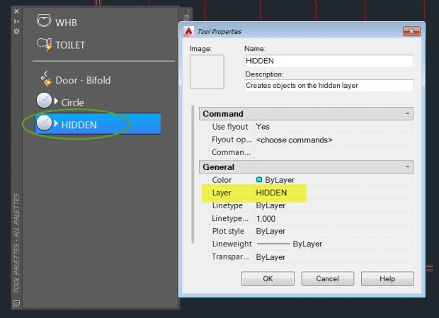
Tool Palettes are designed as a container to hold frequently used content including blocks, images, and geometry commands. What’s great about Tool Palettes is that you can assign layers to the tools so that as the tool is used if the layer doesn’t exist it will be created.
For example: You markup drawings digitally placing all text, lines, polylines, and revision clouds on a layer named MARKUP. This layer is not part of your standard template as it is only used when the drawing is actually marked up and reviewed. You can create a button in the Tool Palette for the Revision Cloud so that each time it is used the MARKUP layer is automatically set current for that operation. If the layer does not exist it is created.
Design Center
The Design Center is used to share content between drawings, and the content is accessible from any drawing without having to open it. This includes layers which can be dragged-and-dropped into any drawing adding the layers to the drawing. Working with a set of drawings from a vendor that is missing some of your standard layers? Add them from any of your drawings or your template using the Design Center
Blocks
Blocks can be inserted into any drawing providing a great way to standardize symbols across your drawings. But are you aware that you can also use blocks to add layers to your drawings? Insert a drawing which contains the layers you want added to your drawing, but don’t actually pick an insertion point. After you click OK to the insert dialog hit ESC on the keyboard to cancel the operation. The drawing is not inserted into the drawing, but its layers are! For more details on this, and the macro to create a button, take a look at the article Edwin Prakoso (@EdwinPrakoso) did over at CADNOTES
Scripts
I’ve started to realize that I’m getting old… not John Evans old, but getting there. Going through Tech School one of the first things we learned after learning the basics was building scripts. Scripts are a very easy method to program and script a list of commands, especially when your programming knowledge and experience is limited.. Now a days scripts are kind of the forgotten language with .NET and Python and all the rest… but when it comes to layers there is still a place..
Before we look at scripts lets look at a couple other things: (1) building layers from the command line and (2) creating a button to create a layer
-layer
There are a couple commands in AutoCAD that can be accessed from the commandline by proceeding the command name with a “-“. Take for example the layer command as if you type layer and hit enter the Layer Manager is displayed. However if you type -layer and hit enter then you are prompted with options on the commandline, no dialog. This is important as if you want to create a button to build a layer, or a script to create a collection of layers you’ll need to use this form of the layer command
New Layer with a Button
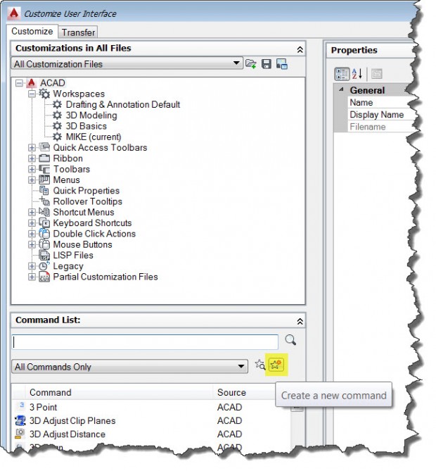
Type CUI and hit enter. This will start the Custom User Interface environment, where you can create toolbars, ribbons, menus, and commands. Navigate to the Commands area and click the button to create a new command.
For now ignore the name, description, and other settings of the command and focus on the Macro. Macros start with ^C^C which basically represents two cancels so that any command you may be in will be cancelled when you start this command. As a space in the Macro will be interpreted as a enter I will follow the ^C^C with a _. We want to create a new red layer called MARKUP so here is the macro….
^C^C_-layer;m;MARKUP;color;red;;;
I’ve used “m” for make as it will create the layer if it doesn’t exist but proceed (not error) if it does. The ; represents an enter. Using this command I can quickly create a new layer, which is red, called MARKUP. I could continue and add MTEXT; to the end so that in addition to creating the layer it also starts the MTEXT command with MARKUP set active.
Creating a Script
Scripts are not really different than the Macro we created for the command in the above section. With a script you can use any command you can access from the commandline, dialogs are off limits. What do I need? A pen, a piece of paper, and notepad.
Start with AutoCAD and step through the sequence of commands you want to perform, writing it down with the pen on the paper, including each time you hit enter. Most scripts fail as you forget to add the right number of ;
In notepad we will create our script. The file is saved with a .scr extension. To run the script in AutoCAD goto the Manage Tab of the Ribbon and select Run Script.
Now we want to create a script that adds three layers to any drawing, in this case specifically for markup and review. Here is the script contents
-layer
make
MARKUP
color
redmake
REVISIONS
color
greenmake
NOTES
color
cyan
That’s it. Run this script and three layers will be added to the drawing.


